Battery with charger
There will be series of simple(r) circuits for my new electronic course for elementary school. For start we need power source. Batteries are fine until flattened out, therefore it’s good to have rechargeable one. I took MCP73831T-2ACI/OT, added micro USB connector and switch to select between charge/discharge mode. In the charge mode, the output is connected to +5V input supply. The power is delivered to the charger via micro USB connector, which means eny mobile phone USB supply will do the job. The charge current is limited to 2A and battery cell has integrated protection circuit. I will add 3D printed housing for the complete pack after the testing of first prototypes.

Prototype of the battery pack
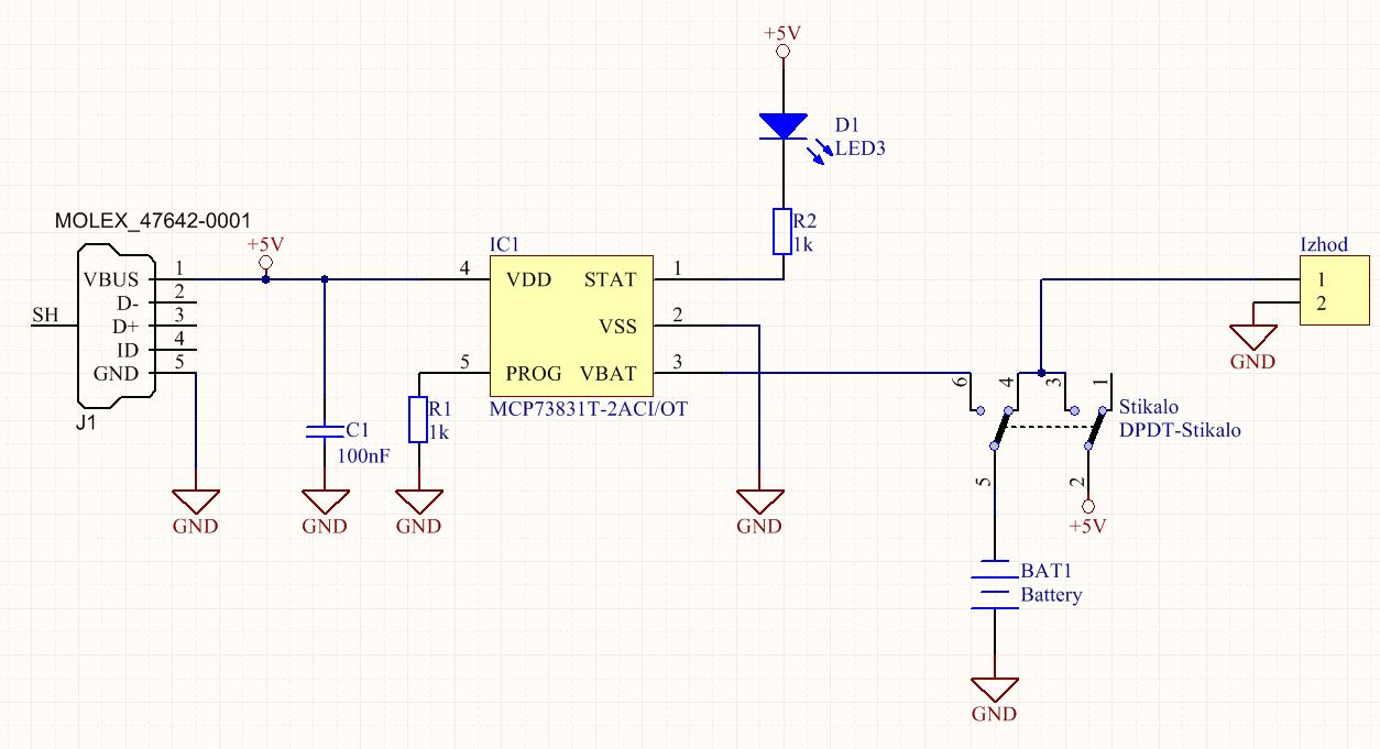
Simple USB battery charger – Schematic

Simple USB battery charger – PCB
Here is PDF of the final TOP layer artwork for “Toner transfer” PCB production in home workshop.
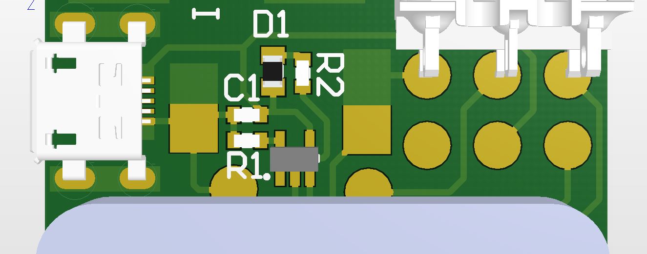
Simple USB battery charger – assembly (component placement)
After first prototype I changed PCB a little and assembled final version:
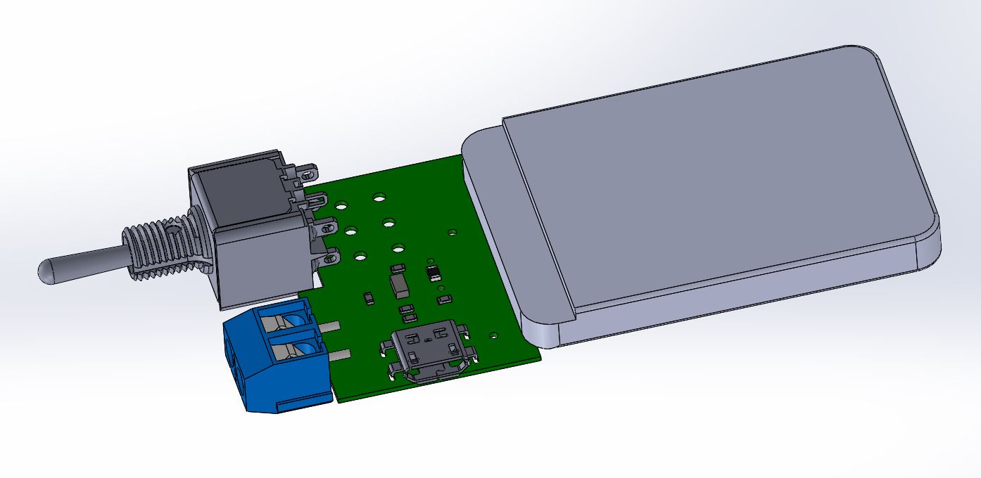
Final assembly
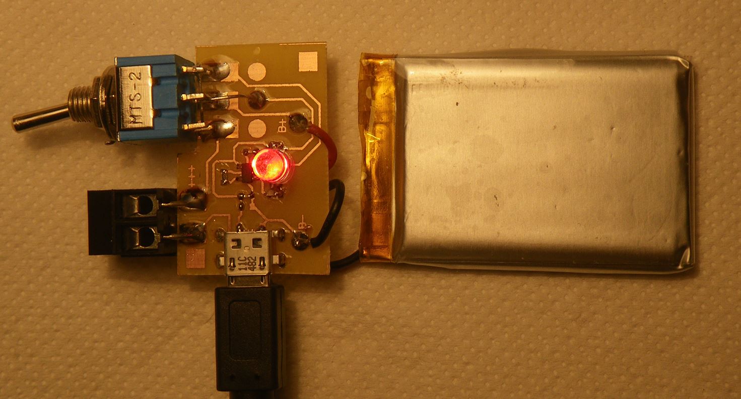
Completed module is working
The chip claims to charge at 500mA max. How did you manage 2A charging current. BTW, switch connects the battery directly. There seems no protection for flattening the battery. Do you mean the battery has the necessary circuits?
1. The charge current is set by resistor at the prog pin. For 500mA, the resistor is set to 2k (Ichg = 1V/Rprog).
2. The battery cell has own protection circuit. There should be another switching circuit in the electronic circuit to disconnect the battery.