Quadruple BDC motor driver for robotics
Once finished (deadline is end of January) this project will become open-source software and hardware.
My quadruple BDC driver for supports up to 4 brushed motors with encoders. Each motor is controlled by its individual closed loop and individual PID gain settings. Additionally, motor speed can also be individually addressed. Analog part of the driver is based on DRV8701P predriver and is controlled by STM32F4 microcontroller.
Specifications:
- 35 V max input voltage (recommended up to 30V)
- 13 A max continuous motor current (recommended up to 10A)
- 50 kHz max encoder pulse frequency (recommended 30kHz)
- Serial communication
- ROS compatible with available library
- XT-60 power connector
- XT-30 motor connectors
- XH2.54 connectors for encoders
- Adjustable current protection (0.1A – 13A)
- Adjustable current alert (LED or on serial)
- Temperature protection
- Hardware emergency stop
- RGB LED for status report
- Extra 24V power switch for external 24V load

BDC driver supports up to 4 motors and simultaneously controls them with PID closed loop
Schematics
The circuit is divided in two parts. The analog power part and the digital part with peripherals. Let’s talk about the power side firstly.
Power side
Everything is based on DRV8701P integrated circuit that takes care of dead times, gate currents and ensures higher voltage for opening high side n-mosfets. The DRV has four control inputs. One is sleep (it is used for emergency stop) and two are PWM signals for forward or reverse drive. The DRV also features braking (though not regenerative) with both PWM signals on at the same time. The fourth control input is reference voltage for limiting the current.
The DRV has shunt amplifier built-in with fixed gain of 20. This is ideal for current sensing with a 10 mOhm shunt resistor. Once the voltage on the output of the shunt amplifier exceeds the voltage reference set on the control pin the driver enters so called current chopping mode in which it effectively limits the motor current to set level.
The driver measures voltage drop across transistors and immediately enters fault mode when the drop is too large. It also features internal temperature protection.

(1) Power side of the BDC driver
The schematic (1) is only for 1 channel. The actual circuit board has 4 identical ones.
Digital side and peripherals
Digital side is based on STM32F4 microcontroller. I used one in QFN housing to make it more immune to possible mechanical vibrations. The microcontroller is generating 8 PWM signals at 21 kHz with 1000 sections (10bit). The encoders are read by interrupt active pins. All four motors work in PID closed loop. Some additional features are motor sensing motor current, input voltage, used energy and temperature sensing.
An RGB LED indicator is present on board to provide basic information about the driver state.
- Blue LED indicates whether the driver (as a unit) is in sleep mode and motors drives are disabled.
- Red LED blinks with a fault code and indicates a possible problem.
- Green LED indicates whether one of the channels is braking.
The board has got a connector for remote emergency stop switch. A relay or NPN/n-channel transistor can also be connected on this input to work as an emergeny stop with external watchdog module.
Two small 1 A buck switching regulators take care of providing 3.3V and 5V from the input supply.
Additionally another N-channel MOSFET switch is implemented. It can switch currents up to 20A.
The communication with the driver is based on UART. User has multiple write registers (to set motor speed, PID gains, etc.) and multiple read register that will contain information about temperature, used energy, encoder ticks, etc. Scroll down to software section to view register-map.

Digital side of the driver with peripherals and power management
Power management
There were some problems in first two revisions with step-down converter supplying 3.3V to the MCU. The switcher would randomly burn and take the microcontroller with it. Since I couldn’t figure out what was the problem in the first two revisions, I chose to implement a solution with different step-down regulators. I chose LM53601 because it supports up to 35V (all other components are also rated for 35V) and is for automotive use which is perfect for my application. There are two step-downs on board. One is supplying 3.3V to the MCU and other peripherals while the second one provides power for encoders (5V). Both are rated for 1 A.
Circuit board
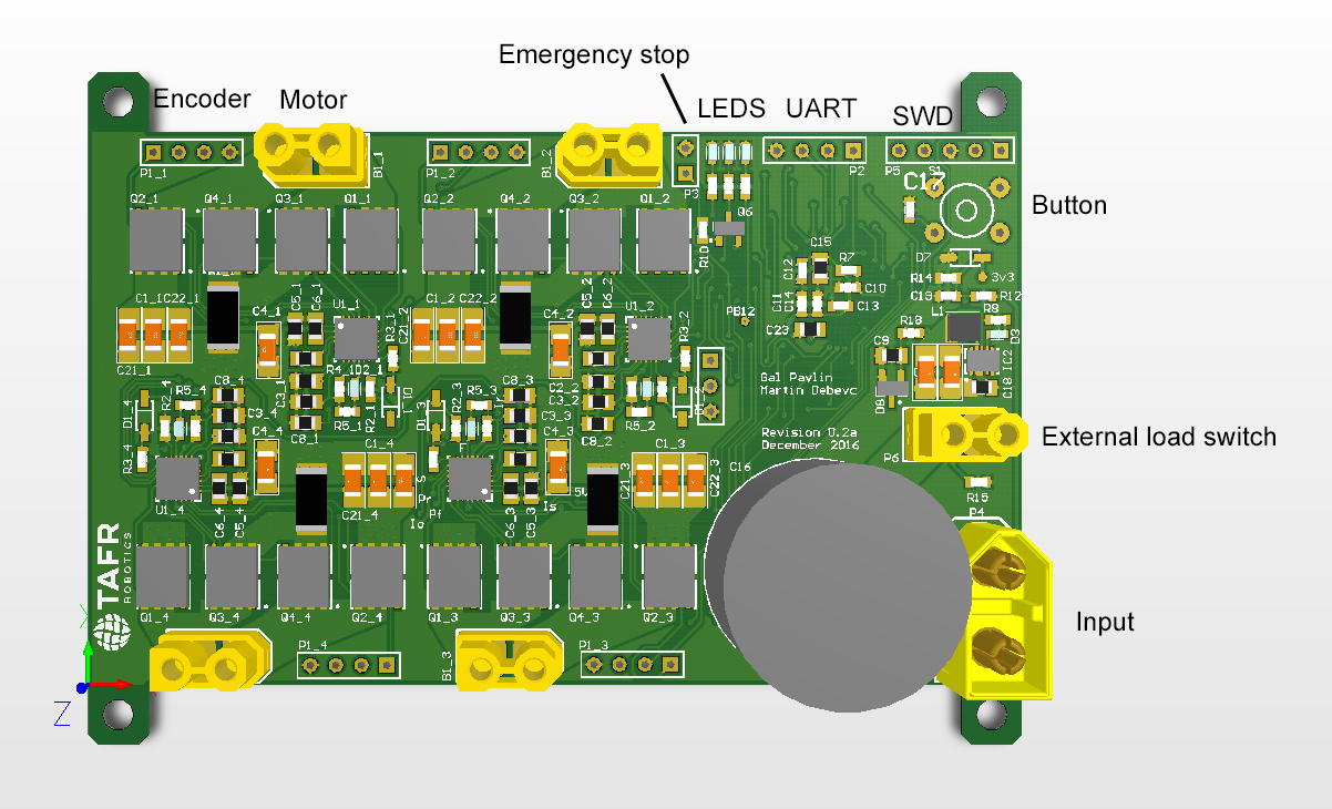

Pictures of the PCB

Revision 0.3 – top view
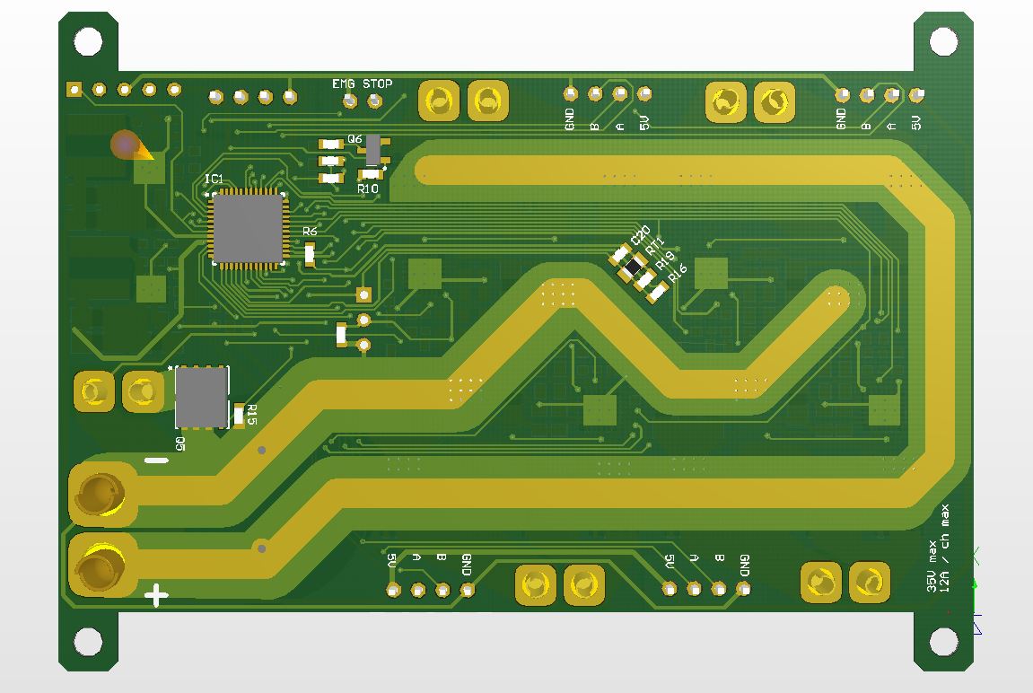
Revision 0.3 – bottom view
Connection diagram
Click on the picture to open the connection diagram in PDF format.
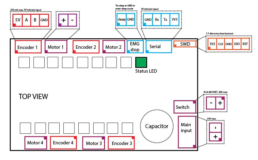
Connection diagram
Software
Most of the software has already been written.
What can the driver do:
- Control the motors in open loop with duty cycle in both directions
- Read the motor speed from encoders
- Control the motors in closed loop in both directions
- Read temperature
- Read motor current
- Read input voltage
- Calculate used energy
- Transmit/receive data over serial port
- Register map
- Adjustable under-voltage and over-current protection
- Fault code
- Startup routine (beeping and such…)
- Active breaking (routines for active braking in PID regulation)
- Adjustable UART timeout (driver enters sleep mode if no UART packets are received in specified time interval – used as an fail-safe feature)
To do:
- Regenerative braking
- Encoder timeout (fail-safe in encoder failuire event)
- RGB LED status report
Register map
Click on the picture to open register map in PDF form.

BDC driver register map
Example command that sets motor 3 speed to “10”:
0x7e 0x83 0x00 0x00 0x27 0x10 0x1f 0x83 0x7e

Explained:
0x7E Start of frame
0x80 Address byte - 10000011 in binary - MSB bit sets the write command, address is 6 lsb bits - in this case the address is 0x03
0x00 Data byte 0
0x00 Data byte 1
0x27 Data byte 2
0x10 Data byte 3 0x00002710 translates to 10000(dec) Note: the actual parameter is multiplied by 1000 / set speed is divided by 1000
0x1F CRC byte 1
0x83 CRC byte 2 More about CRC: https://www.lammertbies.nl/comm/info/crc-calculation.html
0x7E End of frame


The driver then returns:
0xC3 or 11000011 in binary:

Bit7 (msb) indicates that an write command was executed.
Bit6 is acknowledge bit which is also set to 1 - the parameter was in range and set accordingly.
Bit5:0 is addres - in this case it indicates which register was set.
Click on the picture to open example frame in PDF form.

Command frame
More soon…
Gal, zelo lepo si tole spisal 🙂 #proud hehe
very nice job!