Raspberry Pi breakout board with ESD, PoE and Cortex M0
This is Raspberry Pi GPIO connector breakout board with some additional features:
- “Real” or “passive” PoE with 12V output
- 5V DC/DC module
- Additional 3,3V regulator
- ESD protection on all GPIO pins
- two additional pins for each pin on R.Pi 40 pin GPIO connector
- Separate UART and I2C headers
- 3,3V Supply for periphery is selectable: from R.Pi or from external regulator
- STM32F070 or similar in TSSOP-20 housing for controlling additional sensor or any other hardware
- Jumper for Cortex-M0 / R.Pi UART connection

First prototype
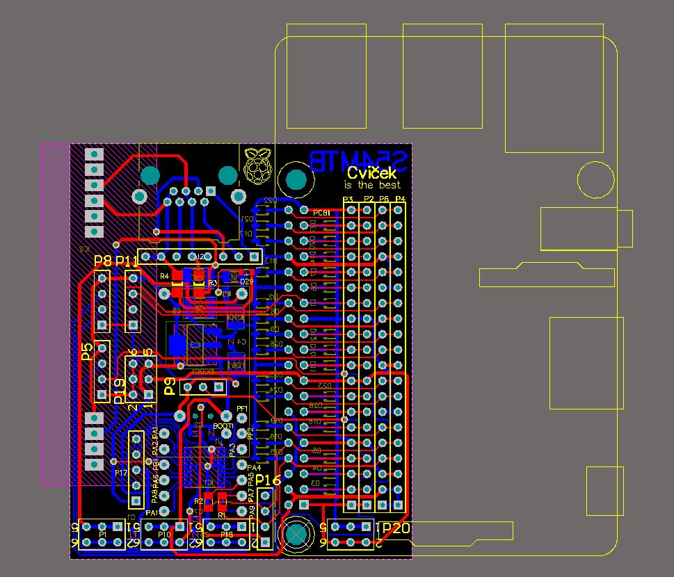
Top view of the PCB with R.Pi contour
This is revision 1.0 – work in progress and the PCB boards are not yet produced (the order is out). For now I will briefly explain the schematics.
Power supply

Power supply section
The power supply is based on Silvertel Ag9700 PoE module. It is IEEE 802.3af compliant module with 12, 5 or 3V isolated output (1500V barrier) delivering 12W of power when proper PoE injector is used. Input voltage has wide operating range. I bought samples via distribution and the price was about 8 EUR per module.
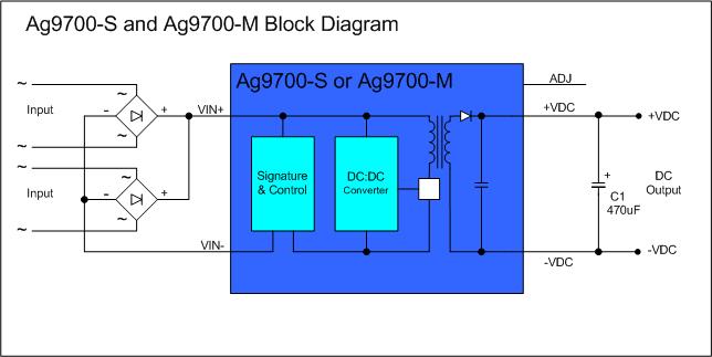
Ag9700 Block diagram (drawing from Silvertel web page)
If this price is too high, there is “Ghetto” option for “passive” PoE. It simply connects unused twisted pairs to the input of the 5V DC/DC. Unfortunately with such solution there is no galvanic isolation. Two 0 ohm jumpers are provided for this: R3 and R4. They can be replaced with fuses as well.
Ethernet
Few words about ethernet connection:
The cable from the outside is connected directly to the heaqder without the RJ45 cable connector. I did this way for simpler installation in the IP65 plastic or metal housings. I put one RJ45 female plug to connect the R.Pi ethernet through short (5-10cm) patch cable.
Cortex M0
Next section is microcontroller. It has SWD debug header and all pins connected to 100 mils headers. The UART PA2/PA3 can be connected to R.Pi UART GPIO14/GPIO15 via two 0 ohm jumpers R1 and R2:
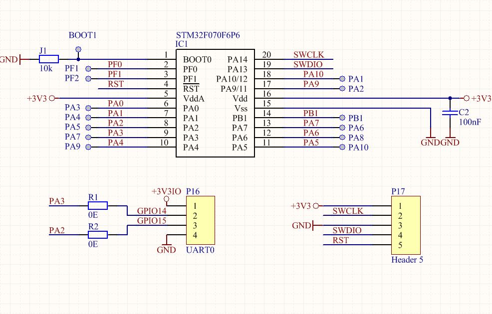
Microcontroller section
Headers
And finally, there are headers for I2C0, I2C1, 1 wire, UART0 and selecting header for 3,3V supply:

IO port headers and power supply selection
The PCB is 56x68mm and slightly covers the display connector of the R.Pi. Other connectors are free.
There are additional pads with +3,3V, +5V and +12V as well. Please check the complete schematic for further details.
PCBs were ordered from PCB Way. They arrived in less than a week. After that, the fucking customs clearance took another week.
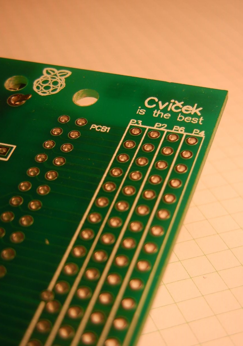
Let’s taste some Cviček(!)
Cviček is good when hands are shaky. It helps soldering better.

Assembled board
After measuring voltages (5V at least), the R.Pi was connected and boot-up.
The ping to the gateway has shown nothing wrong. The beast passed the test. Let’s make some really fun stuff with this now 🙂
pi@civ_1:~ $ ping 192.168.1.254 PING 192.168.1.254 (192.168.1.254) 56(84) bytes of data. 64 bytes from 192.168.1.254: icmp_seq=1 ttl=64 time=0.492 ms 64 bytes from 192.168.1.254: icmp_seq=2 ttl=64 time=0.400 ms 64 bytes from 192.168.1.254: icmp_seq=3 ttl=64 time=0.366 ms 64 bytes from 192.168.1.254: icmp_seq=4 ttl=64 time=0.375 ms 64 bytes from 192.168.1.254: icmp_seq=5 ttl=64 time=0.386 ms 64 bytes from 192.168.1.254: icmp_seq=6 ttl=64 time=0.334 ms 64 bytes from 192.168.1.254: icmp_seq=7 ttl=64 time=0.363 ms 64 bytes from 192.168.1.254: icmp_seq=8 ttl=64 time=0.358 ms 64 bytes from 192.168.1.254: icmp_seq=9 ttl=64 time=0.378 ms 64 bytes from 192.168.1.254: icmp_seq=10 ttl=64 time=0.357 ms 64 bytes from 192.168.1.254: icmp_seq=11 ttl=64 time=0.361 ms 64 bytes from 192.168.1.254: icmp_seq=12 ttl=64 time=0.355 ms 64 bytes from 192.168.1.254: icmp_seq=13 ttl=64 time=0.251 ms 64 bytes from 192.168.1.254: icmp_seq=14 ttl=64 time=0.266 ms 64 bytes from 192.168.1.254: icmp_seq=15 ttl=64 time=0.298 ms |