Small USB to PTT/CW adapter
In this post, I will first introduce some of the basic technical background of the control of the transmit signal (PTT) and other signals (eg CW or linear activation). The second part will describe the interface development and the final product.
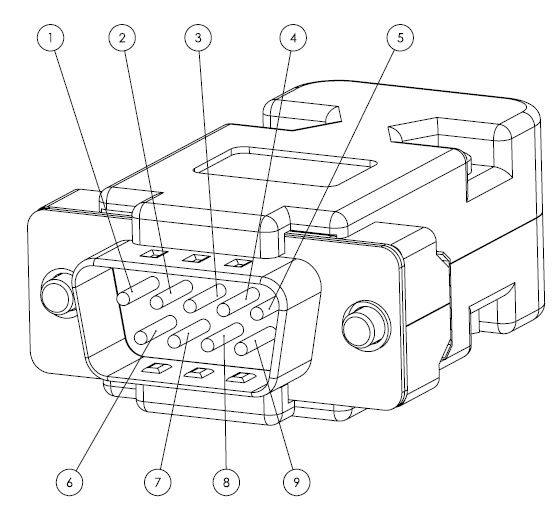
Standard DB9 male connector
Introduction
Newer radio stations have the ability to directly connect to the USB port introducing as a virtual serial interface (Virtual COM port) and a sound card to the host system. Such stations can be controlled by any older and newer programs for ham operation in phonics, telegraphy or digital modes without the use of additional interfaces. Of course, there are plenty of stations of an older date in our shacks, mountain stations, mobile locations and elsewhere that do not have such “advanced” connections. On the other hand, computer equipment and software are constantly updated. Unfortunately, with the new hardware updates, most of the interfaces that have been used by the stations in the past are disappearing. I am referring primarily to the serial RS232 interface or the so called COM port. While ago, we “lost” the parallel printer interface, a.k.a. the “LPT port”. Most of these interfaces have been replaced by a USB port or perhaps some of the wireless interfaces. Of course, older stations do not have to retire. What is needed is the appropriate interface, which will connect older rigs with USB port.
Standard serial interface
Let’s briefly refresh the memory around standard serial interface and how to control the PTT switch with the RS232 interface. On the computer can be either 9 (picture above) or 25 pin D connector
Following table summarize the signals:
| DB9 | DB25 | Name | Function | Direction at host |
| 1 | 8 | DCD | Data carrier detect | In |
| 2 | 3 | RxD | Receive data | In |
| 3 | 2 | TxD | Transmit data | Out |
| 4 | 20 | DTR | Data terminal ready | Out |
| 5 | 7 | GND | Signal ground | – |
| 6 | 6 | DSR | Data set ready | In |
| 7 | 4 | RTS | Request to send | Out |
| 8 | 5 | CTS | Clear to send | In |
| 9 | 22 | RI | Ring indicator | In |
Voltage levels
The RS-232 standard defines the voltage levels that correspond to logical one and logical zero levels for the data transmission and the control signal lines. Valid signals are either in the range of +3 to +15 volts or the range −3 to −15 volts with respect to the “Common Ground” (GND) pin; consequently, the range between −3 to +3 volts is not a valid RS-232 level. For data transmission lines (TxD, RxD, and their secondary channel equivalents), logic one is defined as a negative voltage, the signal condition is called “mark”. Logic zero is positive and the signal condition is termed “space”. Control signals have the opposite polarity: the asserted or active state is positive voltage and the deasserted or inactive state is negative voltage. Examples of control lines include request to send (RTS), clear to send (CTS), data terminal ready (DTR), and data set ready (DSR).
| Data circuits | Control circuits | Voltage |
|---|---|---|
| 0 (space) | Asserted | +3 to +15 V |
| 1 (mark) | Deasserted | −15 to −3 V |
The standard specifies a maximum open-circuit voltage of 25 volts: signal levels of ±5 V, ±10 V, ±12 V, and ±15 V are all commonly seen depending on the voltages available to the line driver circuit. Some RS-232 driver chips have inbuilt circuitry to produce the required voltages from a 3 or 5 volt supply. RS-232 drivers and receivers must be able to withstand indefinite short circuit to ground or to any voltage level up to ±25 volts. The slew rate, or how fast the signal changes between levels, is also controlled.
Because the voltage levels are higher than logic levels typically used by integrated circuits, special intervening driver circuits are required to translate logic levels. These also protect the device’s internal circuitry from short circuits or transients that may appear on the RS-232 interface, and provide sufficient current to comply with the slew rate requirements for data transmission.
Because both ends of the RS-232 circuit depend on the ground pin being zero volts, problems will occur when connecting machinery and computers where the voltage between the ground pin on one end, and the ground pin on the other is not zero. This may also cause a hazardous ground loop. Use of a common ground limits RS-232 to applications with relatively short cables. If the two devices are far enough apart or on separate power systems, the local ground connections at either end of the cable will have differing voltages; this difference will reduce the noise margin of the signals. Balanced, differential serial connections such as RS-422, RS-485, and USB can tolerate larger ground voltage differences because of the differential signaling.[9]
Unused interface signals terminated to ground will have an undefined logic state. Where it is necessary to permanently set a control signal to a defined state, it must be connected to a voltage source that asserts the logic 1 or logic 0 level, for example with a pullup resistor. Some devices provide test voltages on their interface connectors for this purpose.
“Abuse” of control lines for radio control
The RTS, CTS and DTR control lines can be used to control the data flow when used in normal data transmission. Alternatively these three lines can be used as usual digital IO lines with specific voltage levels. By keeping those voltage levels in mind and the control line logic levels (asserted means positive voltge level), the circuit to control the e.g. PTT signal of the radio is straightforward:
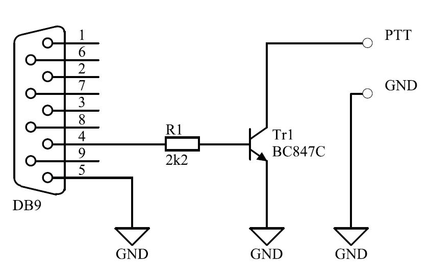
Simplest PTT using serial port
What if our computer does not have a “DB9” connector?
In the introduction I mentioned that certain interfaces disappear from modern computers. The first was “LPT” or printer interface. It was followed by the serial port “COM port”, and it is likely that the computer industry will slowly get rid of other interfaces. Luckily the USB interface stands with legacy support. We are most likely safe for decvade(s) when we make a circuit based on it.
The USB interface is very useful because it can also provide power supply for the devices connected to it. For a low consumption of our interface, the half ampere is more than enough.
The old serial interface is relatively simple regarding hardware connectors, cables, and software programming. The “USB things” are a bit more complicated. After connecting a device to the USB port, a control data exchange is initiated between the USB “host” device (PC) and the connected device. During this initial handshake the newly connected USB device is introduced to the system, which then decide from this data what kind of the device is connected, who the manufacturer etc… These data are written in the form of a 16-bit integer values. The manufacturer’s code is written as Vendor ID (VID) and the devidce is identified as the ProductID (PID). From the VID / PID pair the system selects the appropriate driver (if installed), or the driver can be searched for in a specific location (for example, windows update or the selected location on the disk). In addition to everything else, the driver contains a piece of code that communicates with the given device according to a pre-agreed protocol. In addition to dedicated drivers for specific devices, pre-installed drivers for communicating via USB interfaces are also in use for with commonly used devices, for example, keyboard, mouse, external disk, camera, and so on. In addition to the VID / PID tags, the device also introduce to the the system with the device classification data, i.e. device class. There are some standardized types of devices that are defined by USB standards, e.g. HID (Human Interface Device), MSC (Mass Storage Class), CDC (Communication Device Class), and the like. A typical “HID” device is a mouse, a joystick, or a keyboard. A typical MSC device is a “USB memory stick”. In our case the most interesting is CDC devices specification. The implementation of such a device enables us to produce so called virtual COM port.
Virtual COM port
The interface connected to the USB acting on the “other” side as a serial interface is usually called a virtual COM port. It is not necessary that such a virtual COM port is terminated with voltage level shifters and a DB9 connector. Instead of connecting an external devices with a serial interface, it can be, for example, a software modem that connects to USB. In this case, the “COM port” is terminated within the piece of the software within the microcontroller without real physical access to the lines of the serial interface.
To control the old rigs we are looking for single chip solution with all control line connections. We have several options: we can buy it assembled and packaged in shiny housing (cheap Chinese fake or slightly more expensive “original”), it can be made using a dedicated circuit, or we can use a microcontroller with a USB interface. An overview of some solutions with dedicated circuits is shown in following Table:
| Part # | Producer | Size | ~ Price* | Remarks |
| PL2303SA | Prolific | SO8 | ~2€ | Only Rx and Tx, unobtainable |
| PL2303HXD | Prolific | QFN32 | ~5€ | 8 x GPIO, 12MBps, unobtainable |
| CP2102 | Silicon Labs | QFN28 | 2,3€ | Very popular |
| MCP2221A | Microchip | SO14 | 1,4€ | Has additional GPIO |
| FT232xx | FTDI | SSOP28 | 2,6€ | Most popular, beware of fakes |
| USB2SERA11 | NXP | QFN24 | 2,7€ | Less popular, hard to get |
| TUSB3410 | TI | QFN32 | 4,1€ | Additionally I2C, IrDA, overkill |
| CY7C65213 | Cypress | QFN32 | 1,9€ | Less popular, hard to get |
* based on 100 pcs. from octopart.com
Throw a quick look at the column with prices in the above table, we quickly realize that something is not exactly right. Why is a dedicated circuit that “only” converts the USB interface with its protocol into an asynchronous serial protocol more expensive than one microcontroller that can do the same thing with many other things besides. I do not know the correct answer, but I feel that it is hidden in several reasons. One is surely developing and maintaining the drivers. When , for example, FT232 is connected to the USB, the driver is available through all the standard “distribution channels” of the drivers, and the installation is done automatically in all known operating systems for “100 years” back. The other thing is that they are dedicated circuits, which are not produced as massively as one popular microcontroller. This of course means a higher price per piece.
But then, some “Asian guy” creates a mess with the sale of counterfeits. They usually work but sometimes not. The probability of the trouble usually increases with the approaching contest and most likely the fake FTDI will fail half an hour before high rate contest will start without spare interface and all local shops closed. In the fight against counterfeit, manufacturers are struggling in various ways. A well known FTDI affair is described all over the internet. The driver detected the fake and programmed the ProductID (PID) value of zero making such a fake non operational. Everything looks nice and right, but it was a problem that users did not even know they had fakes, because they were part of the whole devices they bought from various vendors. When Windows systems were upgraded overnight installing FTD drivers update, the next day many devices were no longer working. At the end of the day, there was more damage than good.
USB issues with STM32
During the investigation of possible solutions for this simple interface, I encountered an unsolvable problem with own circuit based on the microcontroller. Beacuse I regularly use the STM32 family of microcontrollers with excellent support, I decided to go with it as the first choice for testing. In the past I made some of my own applications with a virtual COM port (e.g. “Miniature CW keyer“), I designed the PCB and ordered it without any pre-testing. I was pretty sur everything will be OK. When the boards arrived and I assembled them I put “few lines of code” for the test.
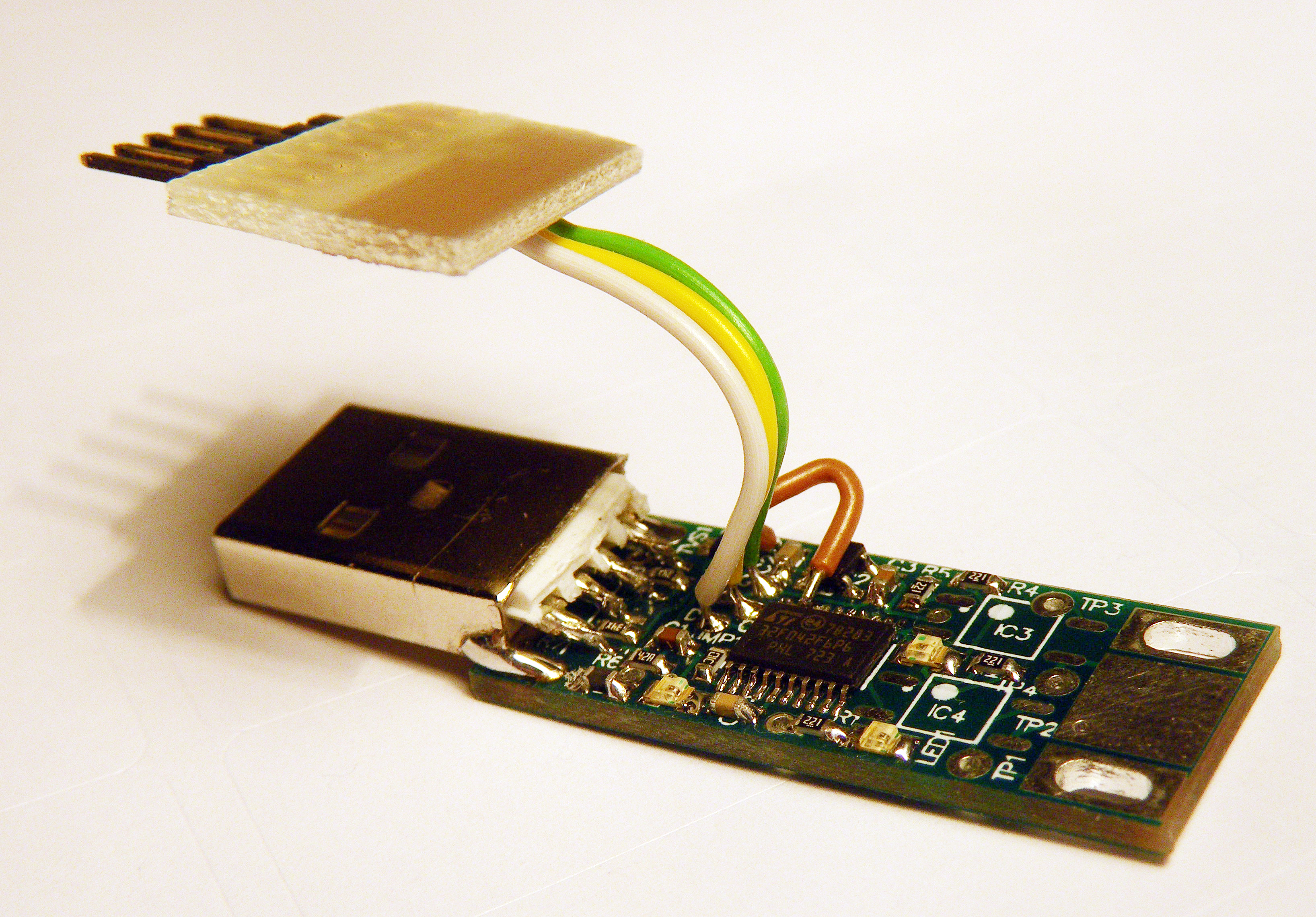
Prototype with STM32F042
Unfortunately the circuit didn’t work as it should during the testing with various terminal programs. The data transfer worked without any issue, but the control lines DTR and RTS were somehow strange. After mor detailed insight into the raw data packets on the USB interface I found out that the packets for controling the DTR and RTS lines do not differ from each other. The problem is therefore probably in the usbser.sys driver, which turns out it has quite a few bugs that are more or less documented.

Equal raw data packet when toggling DTR or RTS
The interface
I made the prototype of the final design on a single-sided board. The schematic is the same as in the FT232 documentation, I added a USB connector to look like usual “USB fob”. The easiest way for test the circuit was with the RealTerm terminal program, which allows manual switching of control lines.
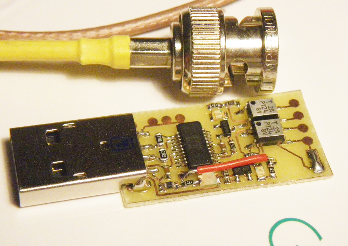
Prototype with FTDI chip
Before making the final design of the circuit I send the module to OM S52AS, who has excellent experience with old stations and always provide helpful feedback. There was was no difference in this case: the control outputs on the FT232RL are inverted for our application (see section above “Abuse of control lines for station control”). It turns out that I have to invert the control lines when directly controlling the open collector NPN transistor. One option was additional transistor and the second was to reprogram the FT232RL using the FTPROG application. This software utility allows changing the configuration including inverton of the control signals, which is an elegant solution and does not require additional components in the circuit. The procedure is described in the FTPROG manual, in section 5.5.
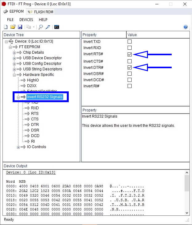
Inverting the control lines with FTPROG
Inverting the polarity is simple: First, the FT232xx interface circuit should be connected to the USB port and the FTPROG program is started. A connected interface appears in the list on the left. In the list, we find the FT EEPROM option and the Invert RS232 signals section below. On the right side, check Invert RTS # and Invert DTR # tick boxes. Finally click on the program icon in the toolbar (small lightning arrow) to store the changes in the internal eeprom of the device.
Is there anything else what HAMs control beside a trivial “PTT” signal? That’s all when the PTT is the only input to the radio station. However, when the station operates e.g. linear amplifier or antenna preamplifier it is necessary to operate those boxes in specified sequence, which is done by software. Furthermore, one of the two output signals from serial port can be used, for example, to control signal for telegraphy. For such reasons I put both outputs on the circuit, both galvanically isolated with optocoupler.
Schematic diagram
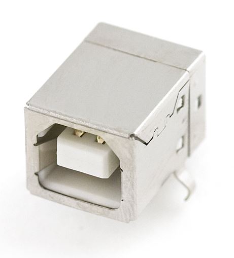
There are two USB connectors J1 and J1a in the diagram. J1 is a type B connector, which connects the interface to a USB cable. The J1a connector is type A, which directly connects the module to the USB socket. There is layout for both. The USB connector is followed by ESD protection to connect to FTDI controller. ESD protection is not protection against the lightning, which would directly hit the antenna and through the station fry the computer.
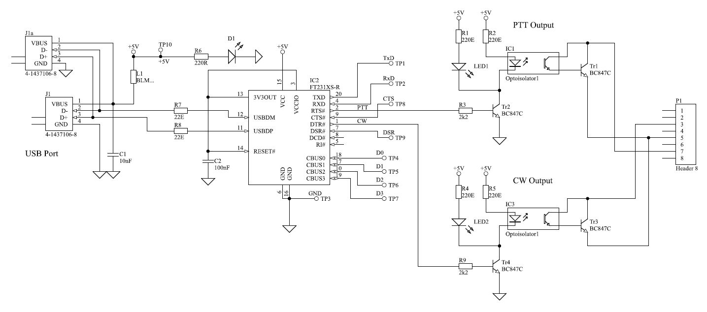
Schematic of the final design
The USB converter is FT232XS-R is low cost device in TSSOP20 housing for easz soldering. In the schematics I followed the manufacturer’s recommendations, especially for capacitors and power supply decoupling. The module DTR and RTS outputs are controlled by two NPN transistors driving LED indicatiors and opto coupler LEDs. Additionally two NPN transistors are added to the galvanically isolated side. They provide output load capability higher than internal optocoupler transistor.
PCB module
The output is connected to the standard RJ45 connector. This simplifies the construction of the cable to connecto the radio station. We can take any network cable, cut it halfway and get two half-made cables to which the radio connectors must be added. It’s not necessary to use the module with RJ45 connector. For such case, there are two bigger holes on the circuit to attach the cable tie that holds the radio cable firmly against the printed circuit board.

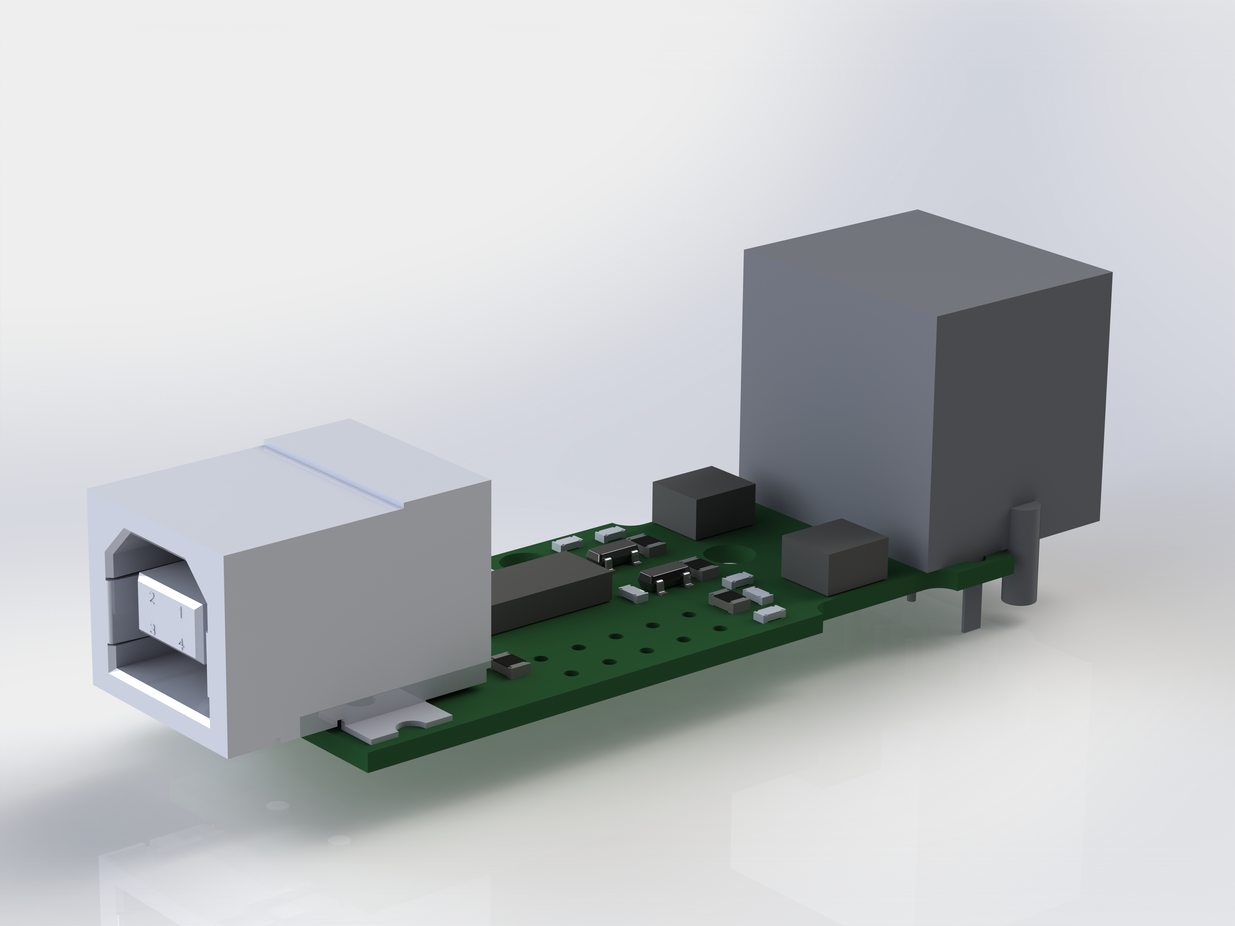
Assembly drawing
Module with RJ45 connector

Module with direct cable connection
Downloads
Altium files can be requested via email.
Gerber files: Download
PDF documentation: Download
Paper from local ham magazine CQ ZRS (in Slovenian language): Download
New PCBs arrived:
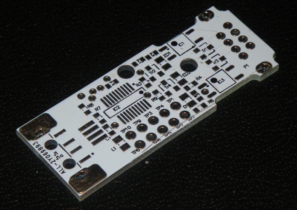
PCB made by AllPCB service
I have PCBs on stock. Price is 1EUR + p&p. Within EU: 1,5EUR (non signed) or 4EUR (signed). Please send me an email to info@pavlin.si if you need one (or more).
Hi !
Some ham applications also use a footswitch input via RS232 control lines (like RI, CTS, DCD or DSR). While you were at it, it would have been useful to add this option.
73 !
Hi! Thanks for the comment. There is another interface under development with sound card and dual serial port including inputs (for foot switch etc). It will be published in short time.
Here: http://e.pavlin.si/2017/12/30/tiny-isolated-usb-to-xcvr-interface-ptt-audio-cat/