Simple small QRO for HF
I followed the ARRL Homberw challenge 50 watt aplifier entry. It is low cost, simple HF linear amplifier designed and built by the author as an entry in the ARRL’s 2009 Homebrew Challenge contest. The requirements of the amplifier were: 40 meter band 50 watt output amplifier intended for use with a QRP transmitter as driver (less than 5W), constructed at a total material cost of not over $125.00.
I redesigned author original design an put it on the double sided PCB with additional output banpass filters. I started with first prototype:

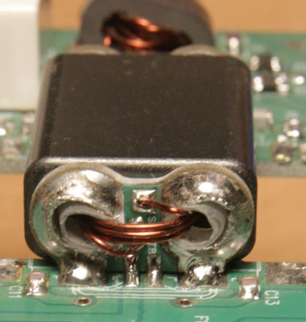
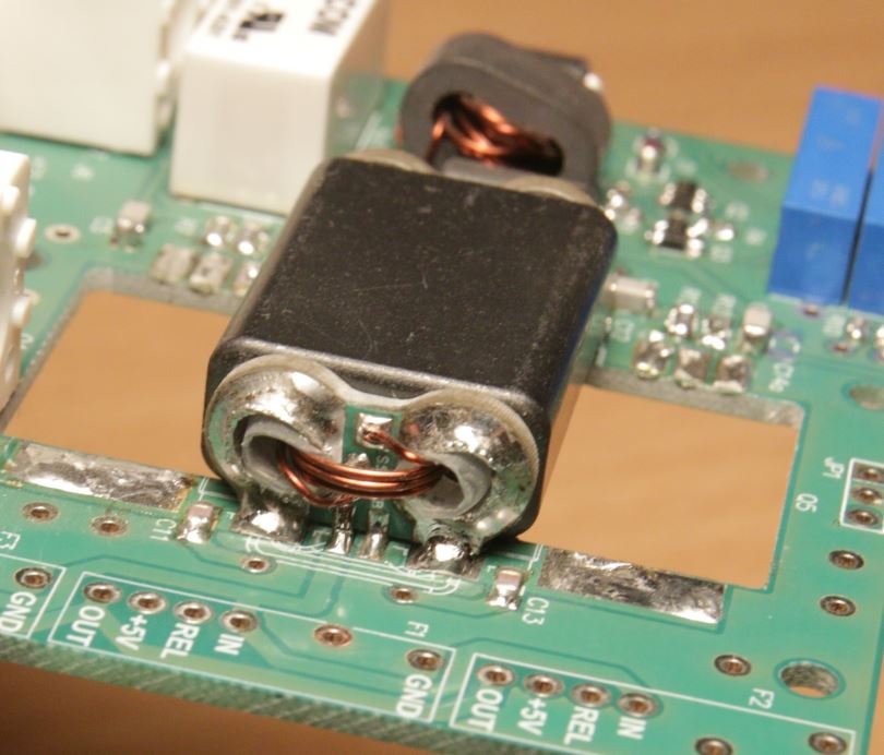
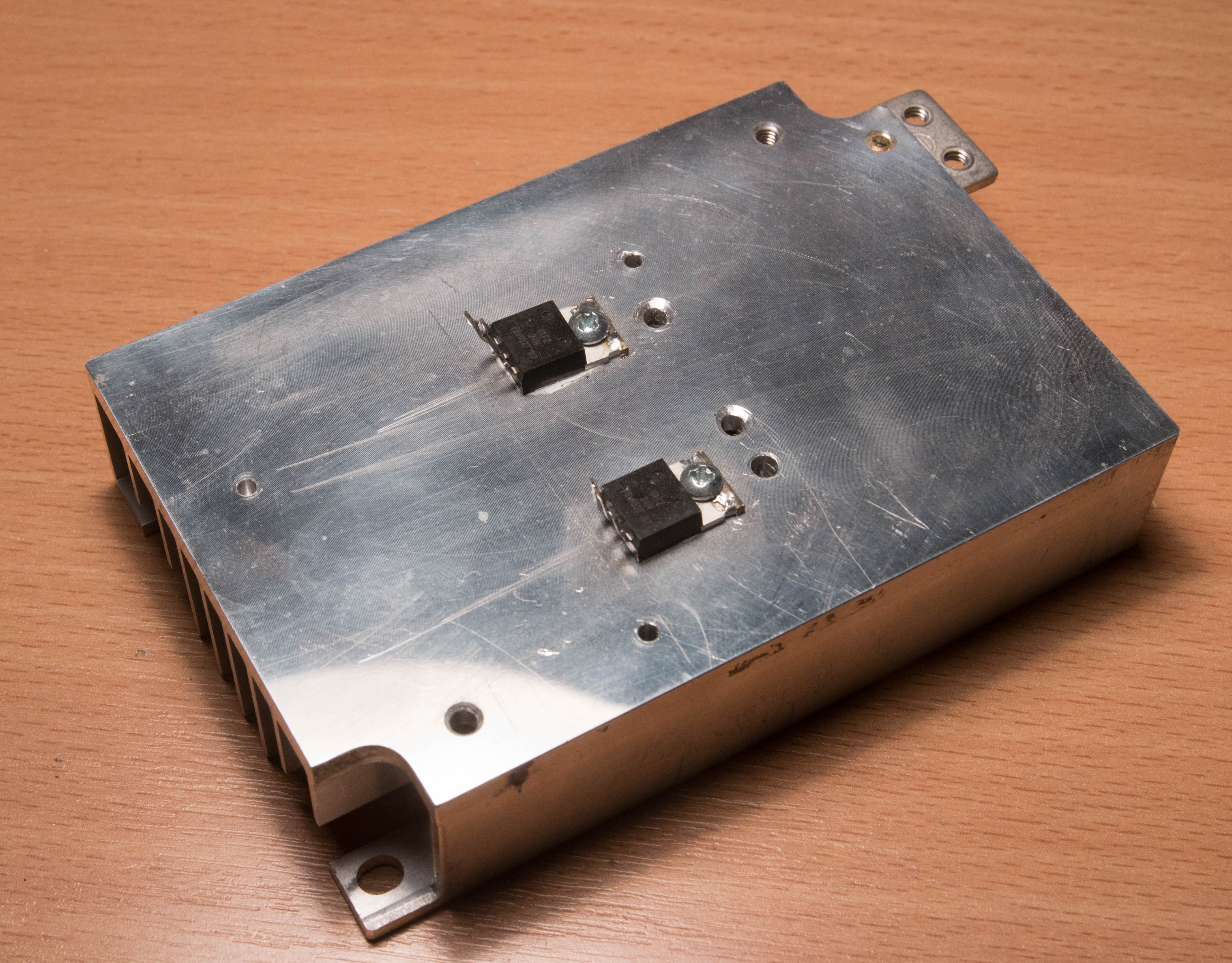
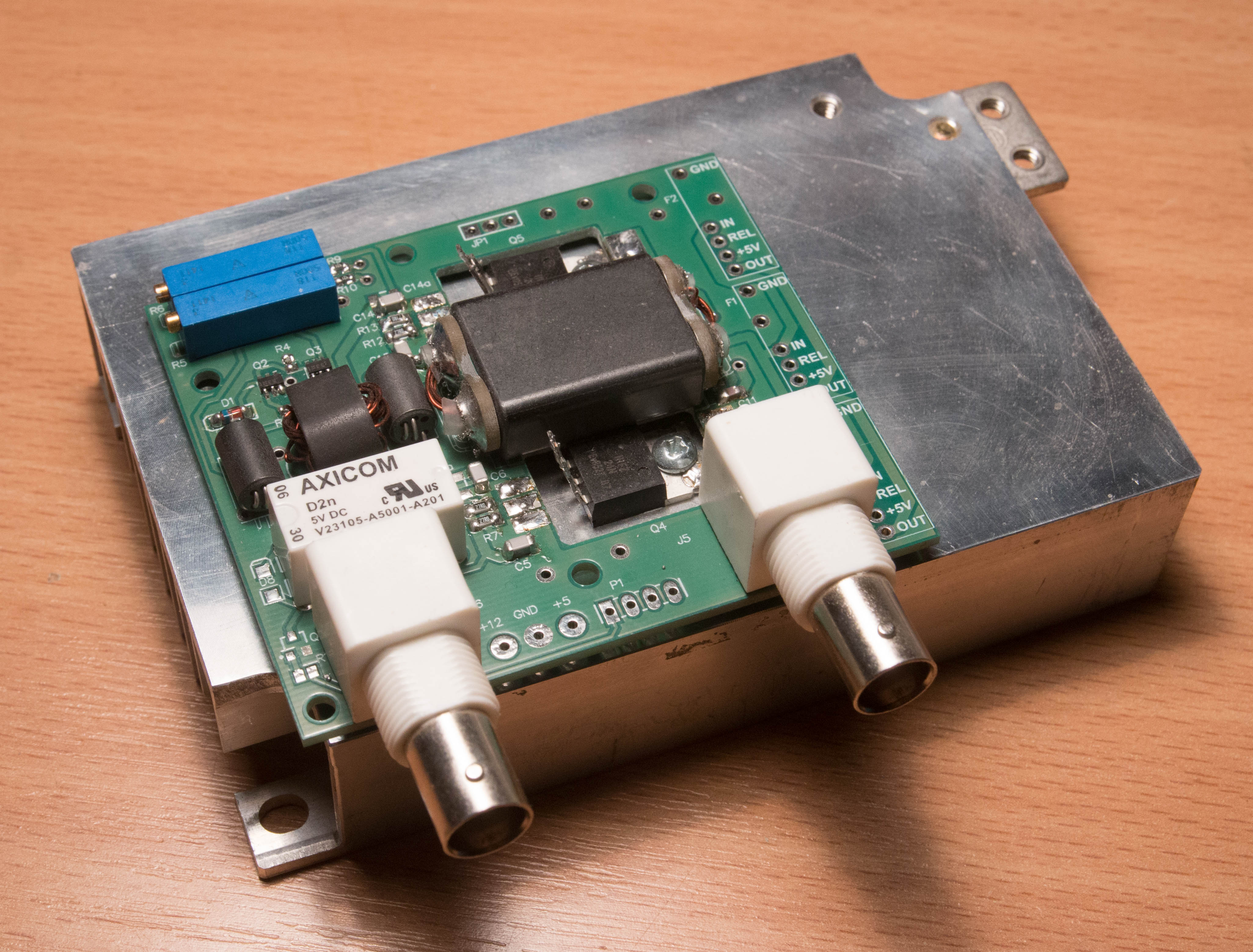
It worked quite well for short periods. Main disadvantage was lack of heat sink. Then I soldered second prototype with proper transistor cooling. I also wound correct transformer using binocular ferrite cores:
Next step was designing PCB. I started with the schematic diagram based on original project:

Schematics in PDF format is HERE.
Final construction of the PCB:


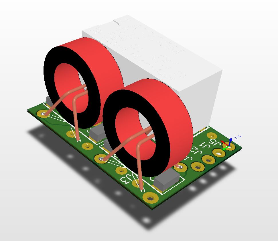
Binocular ferrite is BN-43-3312. There are two small PCBs to make this transformer kind of SMD component. Brass tube with external diameter is inserted in each bore of the BN-43-3312 and then soldered to those two PCBs:
Complete documentation for HF amplifier.
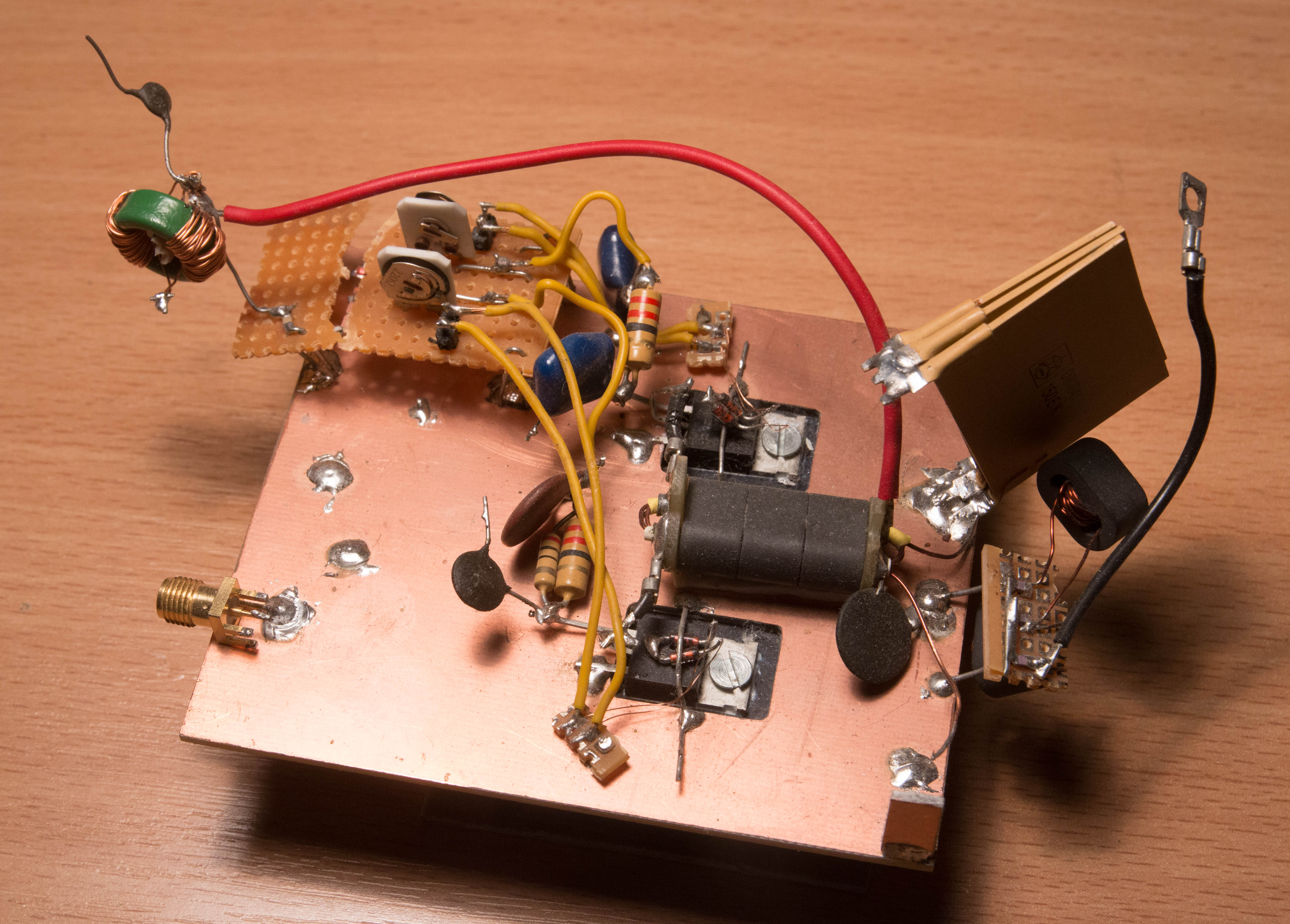
Modules marked as “HF filter” at the output are bandpass filters with the relay to route or bypass the RF signal. Schematic diagram of filters are quite simple:
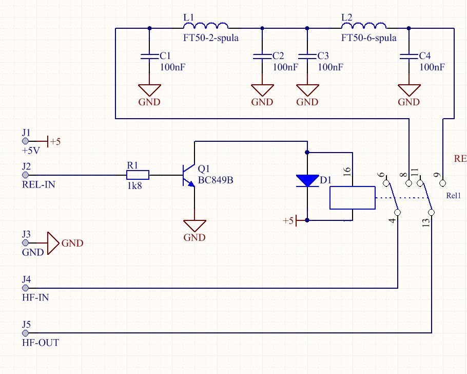
Each filter module looks like this:
The construction details for the filters will be given after first tests.
Complete documentation for Filter module.
This is firs assembled amplifier ready for first tests. HF filters are not attached yet.
I will post updates here — stay tuned!