STM32F4 discovery – Virtual COM port, step-by-step
This is next step in developing applications with STM32F4 Discovery board and Keil tools. This step-by-step tutorial describes how to prepare the simple application which communicates with PC using virtual COM port. This application is based on LED blinky desribed in first tutorial. We will continue with same project. You can copy/paste the entire folder to new one or continue inside the existing “blinky”.
Open or continue editing the project and use the Manage Run-Time Environment dialog to add the USB device driver templates.
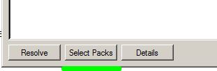
1. First select proper packs versions, click “Select packs“:
CMSIS Version 4.1 contains the CMSIS-Driver API Version 2, which is incompatible with Drivers Version 1. All STM32 Device Family Packs Version 1.x implement Drivers based on Version 1.x and are therefore not compatible. New and existing projects need to be configured to use the newly installed versions of the CMSIS and MDK-Middleware Packs. The new dialog will open.
2. Uncheck Use latest versions of all installed Software Packs.

3. Expand ARM CMSIS and select Fixed version 3.20.4. Expand the KEIL MDK Middleware and select the fixed version 5.1.5. or 5.1.6:
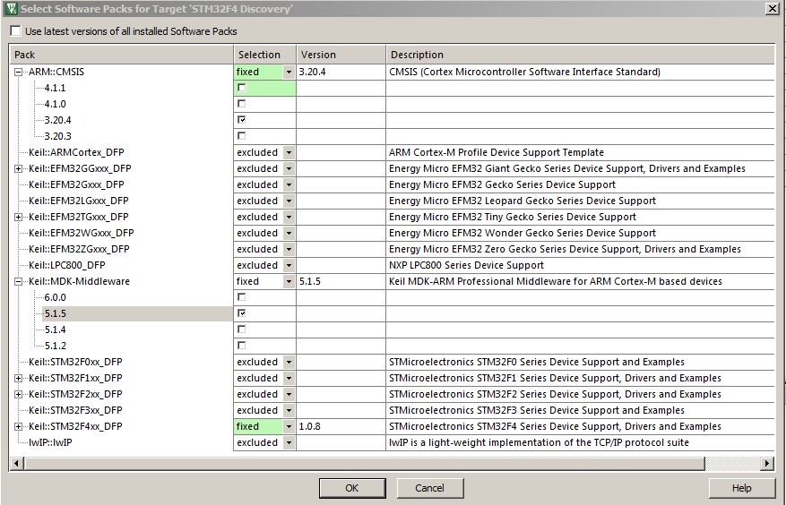
Confirm selections with OK.
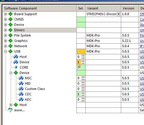
4. Now add USB components to the project. From the USB Device Component select USB Core to include the basic functionality required for USB communication.
5. Set USB Device to ‘1’ to create one USB Device instance.
6. Set USB Device CDC to ‘1’ to create a CDC Device Class instance:
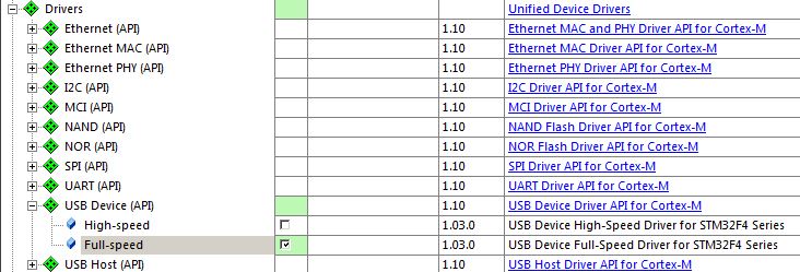
7. Expand Drivers USB Device (API) and enable Full-speed. Click Resolve to clean up the selections:
Click OK. All selected component are now in the project. Next step is Middleware configuration. Every MDK-Professional Middleware component has a set of configuration files that adjusts application specific parameters and determines the driver interfaces. These configuration files are accessed in the Project window. Our CDC Device example, we have two configuration files: USBD_Config_0.c and USBD_Config_CDC_0.h.
8. Open USBD_Config_0.c, select Configuration Wizard and click Expand All. Change Product ID to 0x1C05. Change Maximum power consumption to 500mA. Change Serial number to any value you may want. Leave other values as they were in template:

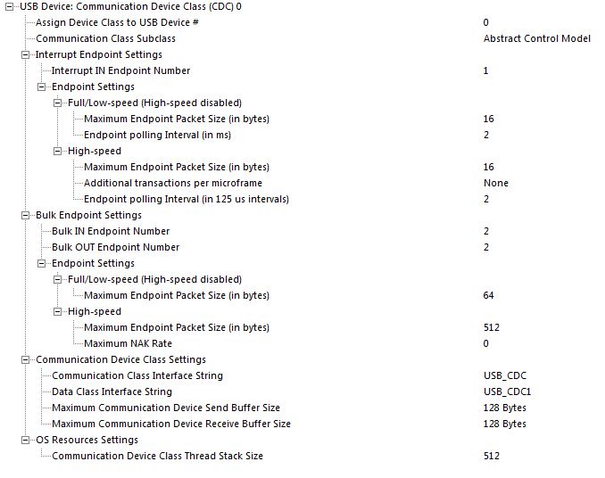
9. Open file USBD_Config_CDC_0.h and change parameters in Communication device class Settings: Buffer size to 128 bytes, Communication Class Interface String to “USB_CDC” and Data Class Interface String to “USB_CDC1”. Final settings should look like this:
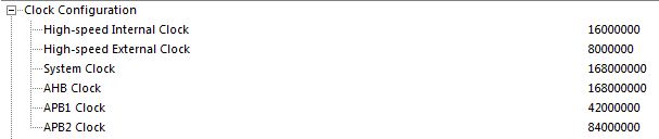
10. Adjust settings for USB in RTE_Device.h. Open the file RTE_Device.h and expand Clock configuration. Set the High-speed external clock to 8MHz (8000000), System and AHB clock to 168MHz (168000000).
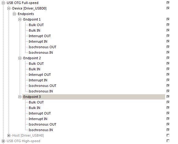
11. Expand USB OTG Full-speed and enable Device. Uncheck (disbale) host. Keep three endpoints unchanged:
12. Adjust the RTOS resources for USB device. The detailed description is in the MDK-Professional Middleware User’s Guide, section “Resource Requirements“. Refer also to “CMSIS-RTOS RTX Configuration” in MDK5 getting started. Open file RTX_Conf_CM.C and expand all in configuration wizard.
Change Main thread stack size to 512, Number of threads with user-provided stack size to 2, Total stack size [bytes] for threads with user-provided stack size to 1024 and Timer clock value [Hz] to 168000000.

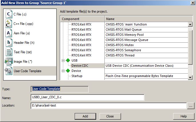
13. Add USBD_User_CDC_0.c to the project: right click on Source Group 1 and use menu option Add new item. Select User Code Template and insert USB Device CDC:
Click Add
14. Add #include “rl_usb.h” to the main.c Add two function calls to the main() function to initialize and connect USB device:
1 2 3 4 5 6 7 8 9 10 11 12 13 14 15 16 17 18 19 20 21 22 23 24 25 26 27 28 29 30 31 32 | /*---------------------------------------------------------------------------- * CMSIS-RTOS 'main' function template *---------------------------------------------------------------------------*/ #define osObjectsPublic // define objects in main module #include "osObjects.h" // RTOS object definitions #include "cmsis_os.h" // ARM::CMSIS:RTOS:Keil RTX #include "led.h" #include "rl_usb.h" /* * main: initialize and start the system */ int main (void) { osKernelInitialize (); // initialize CMSIS-RTOS USBD_Initialize (0); /* USB Device 0 Initialization */ USBD_Connect (0); /* USB Device 0 Connect */ // initialize peripherals here LED_Initialize (); // create 'thread' functions that start executing, // example: tid_name = osThreadCreate (osThread(name), NULL); Init_BlinkyThread(); osKernelStart (); // start thread execution while (1); } |
15. You may compile and download flash. The PC should recognize new device, but it will not work properly, because the PC don’t know which driver to use with our new device. You should use drivers from other CDC examples from “Boards” folder. Since we changed Product ID and other USB device configurations, the *.inf file from C:\Keil\ARM\Boards\Keil\MCBSTM32C\RL\USB\Device\CDC_ACM can be directly used.
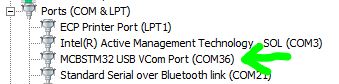
Here are three files required for our CDC example to operqte properly: usb-drv Just unpack those files to some folder and run device manager. Right click on the USB device with yellow sign and use option “Update driver”. Point to the folder with .inf file. The device should be recognised as new COM port:
Next exercise will follow. We will add some commands to control our device.
I tried, maybe this example needs MDK professional? My lite version doesn’t work.
Sorry, I got feedback from other users. Unfortunately the MDKPRO is required due to packs used in this example.
Hi, may I know more about stack setting, according to documentation, Number of threads with user-provided stack size should be 3 for CDC, Default Stack Size should set to minimum 512, “Total stack size [bytes] for threads with user-provided stack size” is “Number of threads” x “Default Stack Size”, so if you set only 2, then your value should be 400 instead of 1024?
400 because your Default Stack Size is 200.
how do you open select packs window(the first screenshot of this tutorial)? I cant find it on my tool bar. Therefore, I ignored that part. Now,i am stuck in step 14 of this tutorial. The problem is that keil doesnt allow me to include rl_usb.h. I am getting the following error and warning messages. Please advice. Thank you.
LED.h(6): warning: #1-D: last line of file ends without a newline
void Init_BlinkyThread ( void ); // Initialize thread
main.c(10): error: #13: expected a file name
#include “rl_usb.h”
main.c: 1 warning, 1 error
compiling LED.c…
LED.c(35): warning: #1-D: last line of file ends without a newline
}
LED.c: 1 warning, 0 errors
compiling USBD_User_CDC_0.c…
USBD_User_CDC_0.c(53): error: #20: identifier “bool” is undefined
bool USBD_CDC0_ACM_SetLineCoding (CDC_LINE_CODING *line_coding) {
USBD_User_CDC_0.c(56): error: #20: identifier “true” is undefined
return true;
USBD_User_CDC_0.c(64): error: #20: identifier “bool” is undefined
bool USBD_CDC0_ACM_GetLineCoding (CDC_LINE_CODING *line_coding) {
USBD_User_CDC_0.c(67): error: #20: identifier “true” is undefined
return true;
USBD_User_CDC_0.c(77): error: #20: identifier “bool” is undefined
bool USBD_CDC0_ACM_SetControlLineState (uint16_t state) {
USBD_User_CDC_0.c(80): error: #20: identifier “true” is undefined
return true;
USBD_User_CDC_0.c: 0 warnings, 6 errors
compiling RTX_Conf_CM.c…
assembling startup_stm32f40_41xxx.s…
compiling system_stm32f4xx.c…
compiling GPIO_STM32F4xx.c…
compiling OTG_FS_STM32F4xx.c…
compiling USBD_FS_STM32F4xx.c…
compiling USBD_Config_0.c…
“.\out\vcp_test.axf” – 7 Error(s), 2 Warning(s).
Target not created
You need proper version of keil tools.
errors…
I made all steps lik in this article.
Can you put here full project?
Sorry, I had HD crash and lost those examples. I will try to get running new version and put it here ASAP.