03.08.2017, 21:54
Embedded board arrays in altium could be used for creating panels for multiplication during prototyping. Here is short illustrative example. In this example we will:
- create single PCB board design (not covered here)
- create and embed array with this single PCB
- add some markers and holes
- add panel cutouts

Final result, keep reading below…
Continue reading ‘Altium – working with embedded boards’ »
13.07.2016, 21:28
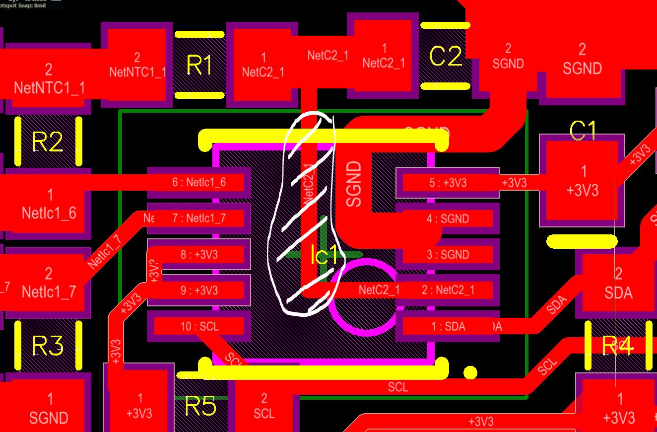
The MCBs (Machined Circuit Boards – an alternative to DIY printed circuit boards) are now jumping out from the mini-CNC like in high volume production. This is new revision of RH/Temperature sensor with RS485 interface with Si7013:

New revision of Si7013 sensor module – machined boards
The boards are solder “plated” and prepared for assembly process. However, there is one issue with Si7013. It comes in SMD housing without leads. This is no big trouble, but the thermal pad is, because there is trace routed under the Si7013, which is not GND:

The “problematic” trace is white hatched.
That means it must not be soldered to thermal pad. The good thing is, the thermal pad can be left floating.
Continue reading ‘Soldering TQFN with a distance’ »
04.03.2016, 13:24
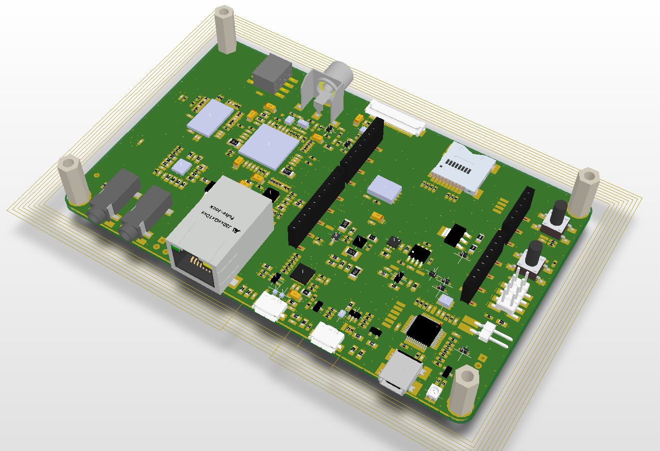
I was searching for 3D model of the STM32F7 discovery board (part number STM32F746 discovery) without success. I ended with my own 3D model.


>>>Here is the project on GRABCAD<<<
And local copy of STEP file: MB1191B-V14
16.07.2012, 18:06
My Archos 10.1 died. The death was not sudden. At first, the charging was slower, after a while I noticed “blink blink problem“. After few days the tablet turned int a brick. I realised it was the time for some action…
Opening Archos 10.1 is fairly simple. There are 6 small torx srews and dozen of plastic clips around the case holding both sides together. To separate plastic parts use your nails or similar “material”, which is softer than plastics to avoid scratches. There is plastic lid covering all side connectors. Camera is within rubber holder and MIC has one rubber cover. Remove all tiny parts into safe place.
 Two flex capton foils connects LCD side with periphery. Wider has dual row connector and narrower, 4 pin ribbon (probably the touch controller) has small connector. Remove orange adhesive tapes and pull the wider ribb on out from the board. Open the small connector (black part up!) and pull out the ribbon. Now warm up your soldering iron and unsolder the battery from the circuit (red B+ wire) to avoid “escaping smoke” effects. Isolate the red wire with some isolation! Continue reading ‘Archos tablet 10.1 repair’ »
Tags:
board,
charger,
components,
electronic circuit,
housing,
internal,
modules,
open,
PCB,
repair,
schematic,
screw,
teardown,
unpack Category:
Android,
Archos 10.1 tablet |
7 Comments
20.06.2011, 21:50
Next simple board in “universal” series is JTAG adaptor. First was Universal USB adapter with power supply. Most commonly used JTAG connector is 20 pin IDC, found on many prototyping boards. It takes lot of board space and requires through hole drilling in PCB, which I usually avoid when building prototypes with single sided PCB, manufactured with toner transfer method.
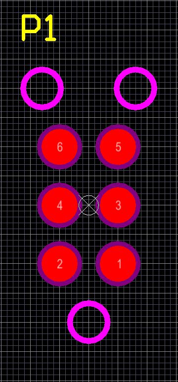
This simple adapter has all neccessary pullups and pulldowns. Connector at one side is standard IDC20, at the other side are 9 pads in line with 2,54mm raster.
Files for JTAG adapter:
Soldered module:

Jtag interface module
19.06.2011, 16:21
This single sided breakout board for Roving Networks RN-171 is intended for DIY testing. Single sided PCB is ideal for toner transfer method. Pins are in two rows with 2,54mm raster suitable for breadboard or direct soldering.

RN171 breakout board
Files for the PCB are here:
15.06.2011, 20:55
 2S Battery pack is very useful. It can be used to supply 5V electronic circuit without DC/DC. With help of a simple boost a 2S battery can drive 3 power LED lamp with reasonable currents. Etc…
Let’s see what is required for reliable, safe lithium polymer batter pack with two serially connected cells (2S LiPo battery pack).
Obviouslly, at least two cells are needed. Unfortunately, LiPo cells are very dangerous if used over specified limits. Most dificult is maximum cell voltage during charge. If cells are aexposed to voltages above 4,2V they can burn, but not at the charging, this could happen at any time after charging. The absolute maximum charging voltage is 4.25V per cell. To avoid burning down the house and other troubles, a battery protection circuit board (PCB) is a must with LiPo cells.
Continue reading ‘2S LiPo Battery pack’ »
Tags:
battery,
Charge,
Discharge,
DS2775,
DS2776,
DS2777,
DS2778,
fuel gauge,
i2c,
LiPo,
PCB,
protection Category:
Batteries,
LiPo protection |
1 Comment