FT991 IPO/ATT FAULT
Yaesu FT-991A Frontend has nasty hidden fault. It is not normal from €1000 radio to stop working just because you use it in a pileup situation or when your close OM is beaming toward you with QRO.
New, out-of-the box radio receive performance of the FT-991(A) was normal, but after other station(s) had transmitted at a higher power levels, the FT-991(A) receiver failed. The failure mode was as follows:
- Receiver operation is normal when the Attenuator feature is disabled.
- Receiver operation fails (no receive and a very quiet noise-floor) when the Attenuator feature is enabled.
- IPO operation enables the Attenuator and results in the same receiver failure mentioned immediately above.
Same issues are reported elsewhere:
- Yaesu FT-991A Receiver Front End Failure
- FT991 frontend gone bye bye
- FT 991 A deaf in IPO mode, receives normally in AMP modes in HF bands
Patient with exactly the same simptoms got to the operation table in my lab today. The owner is OM S52W, very successfull contester and member of the famous contest club.

After removing the lower side of the metal hosing, the microscope revealed the disaster:

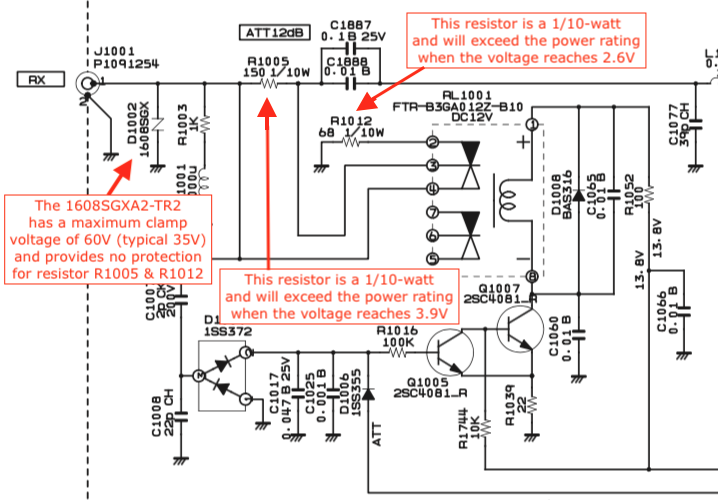
The resistor was not just blown, but broken due to overheating. Something very violent happened here. Before working with soldering iron within the radio it is good idea to remove anything that can melt, especially the cables. There are three on the way (photo is for reference if anyone reading this unplug the cables before taking photo – another good idea prior disassembling):

I removed the remains of the dead resistor body. Because banana is too large for scale, I used SMA connector:

Main problem is described in the COMMS Working Group page:

The R1005 can also be replaced with equal part (beging for the same failure in near future). The above mentioned source suggests replacing the resistor with THT part, which is not very aesthetic. I took another approach. I replaced the 150Ω with 5 parallel 750Ω resistors. Five tacked resistors may have maximum power less than 5 times the power of single resistor due to less power dissipated via convection. But the main path of the heat dissipation is via conduction to the copper traces and PCB substrate. R1005 failure is at least less likely than replacing with single resistor.
Adding more solder to the resistors terminals should maximize heat dissipation to the PCB. The resistor stack is small and doesnt require any additional attachment like THT resistor:

Finally, some cleaning with IPA using cotton swab is highly recommended

To access narrow areas use cotton wrapped around sharp tweezers tip:

And now the final test. The block diagram is as follows:

S meter with IPO path selected:

S meter with AMP1 selected:

S meter with AMP2 selected:

73 de S54MTB
S55A živi na hribu Kampel pri Kopru. Njegova vertikalka je idealna za pobiranja statike in občasne strele. V FT-1000MP MkV sem zamenjal nekaj ducata PIN preklopnih diod, miniaturnih dušilk ter atenuatorskih uporov. Zadnje čase mi pomagal S51PV s SMD mikroskopom in ostalo opremo.
Bolj zanimiva zabava je bila z mojim FT-1000MP, ki ga je strela udarila čez omrežje in CAT kabl. Zamenjana CTRL PCB, 2 x DDS LSI in drugi drobiž. Dela še danes. Pred kratkim otpovedal LSI bit 4 za kontrolo ATU. Žal ne preklapa več releje za tuljave nad 4 MHz.
MX & HNY & GL RF YM de Mario, S56A, N1YU, MSc EE retired
MNY TNX de S54MTB