ST-Link V2 on a single sided DIY PCB
I am using U-Link from Keil for my debugging purposes. Sometimes it is quite bulky. I decided to design STLink V2 on a single-sided PCB in smallest possible size. Here is how it looks:
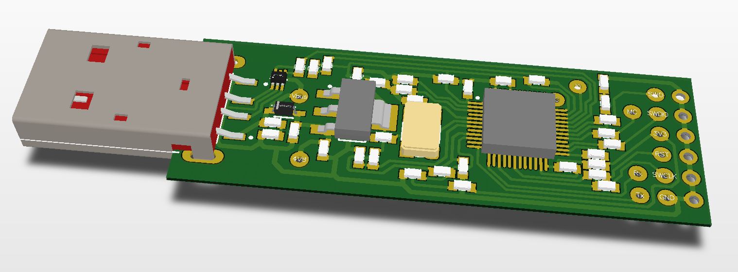
This is preliminary preview. I will post more details after first testing.
For start here’s Comparision from ST-LINK and ST-LINKv2 (check link for great source of STM32 info).

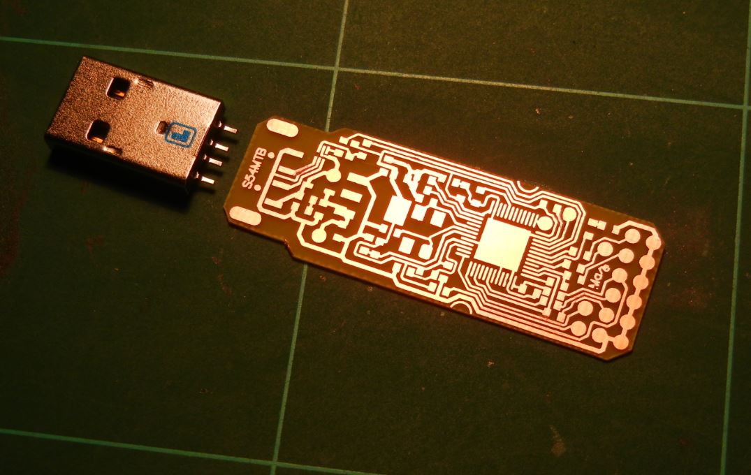
Producing this nice module starts with this template:
stlink V2 DIY PCB CLONE – PDF for toner transfer PCB production
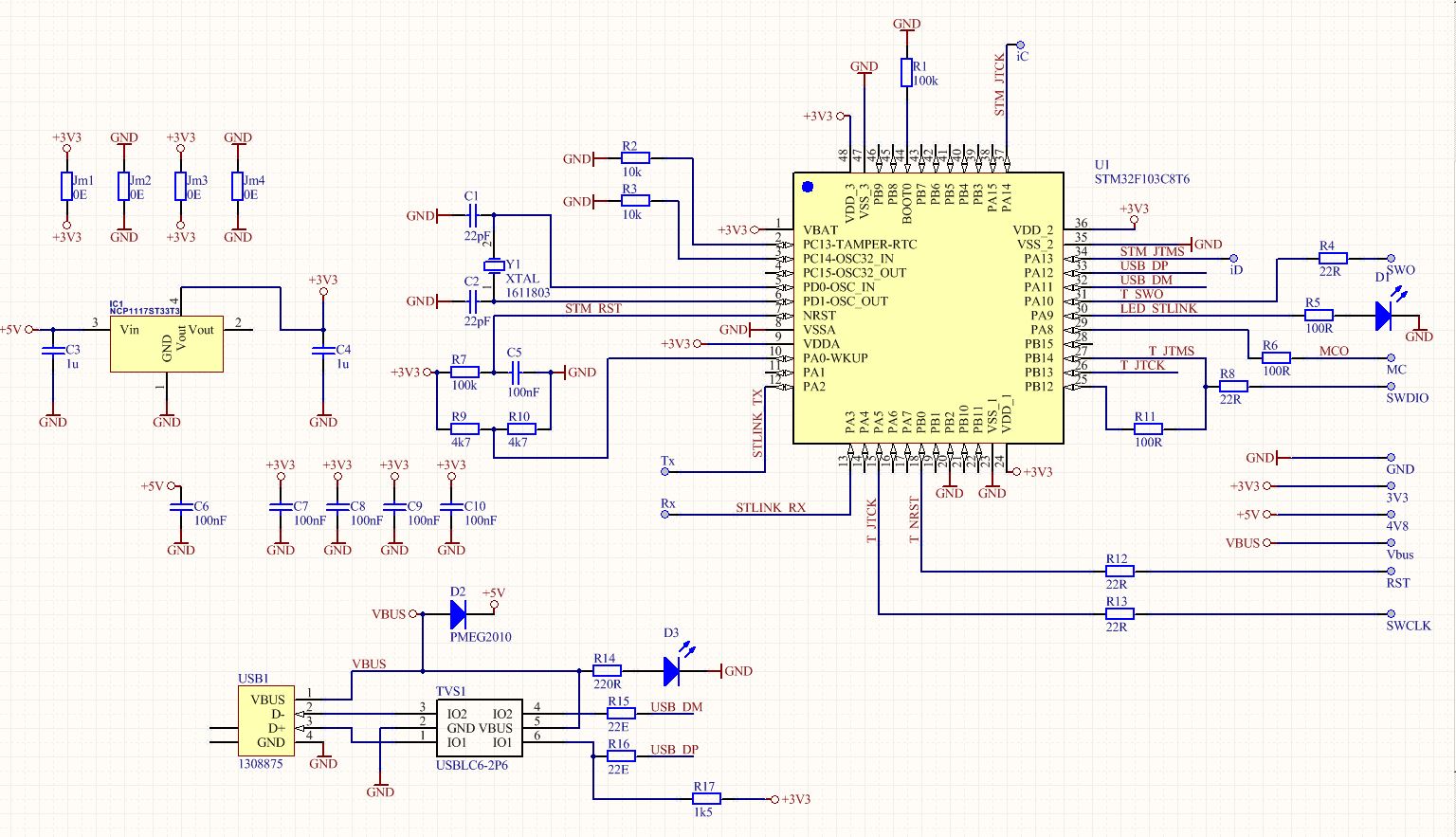
apter transfering to FR4 and etching, the assembly process can start. First, take a look at the schematic diagram for components. I took what I have on stock. Alternatives are possible. The design is not critical.
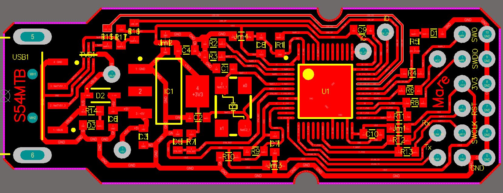
The PCB assembly drawing:
Or, even better, here is stlink v2 minidongle USB module complete documentation in a single PDF file.
Now, the assembly can finally start.
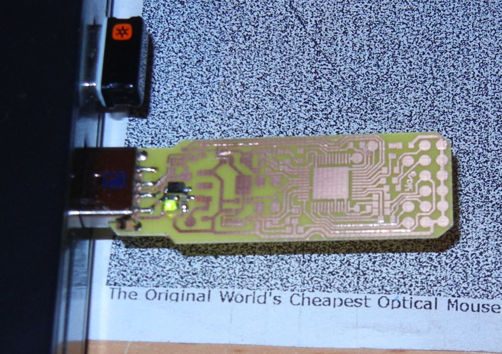
First solder USB connector and LED with resistor to check if 5V is OK:

The LED should turn ON:
Place the 3V3 regulator and check the supply voltage:

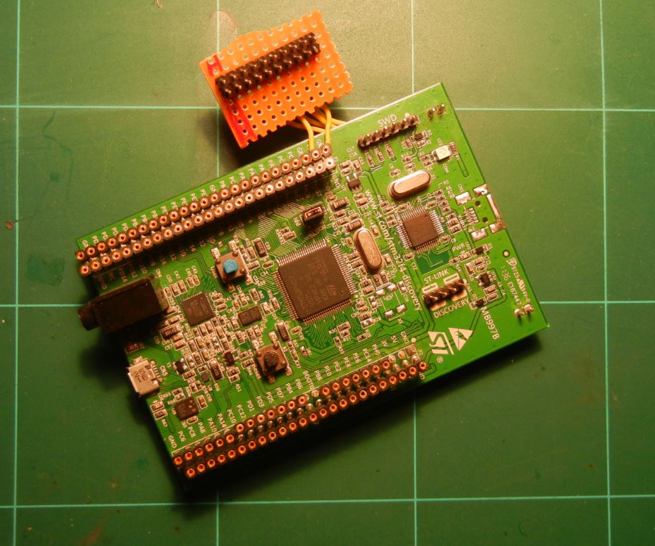
Now is the critical moment. Pick the brain donor from your favorite discovery or nucleo family of boards. I took one old discovery F4, which lived in better times. I replaced the STLINK with 20 pin header to connect directly on U-Link. The Mini USB connector was missing and didn’t know if the STM32F103 was OK or not (it was).

Here’s the patient, the brain donor:
Now it’s time to heat up some air:

And remove the STM32F103 from the discovery board:
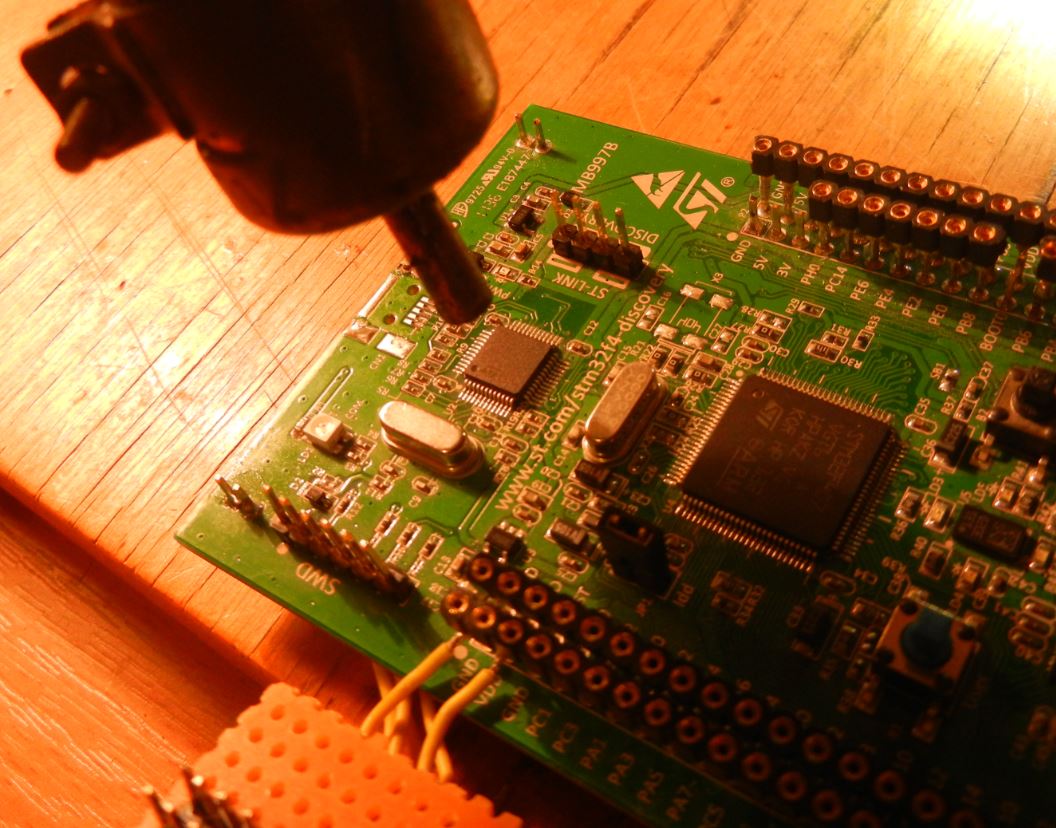
It took just few minutes and the microcontroller was removed:

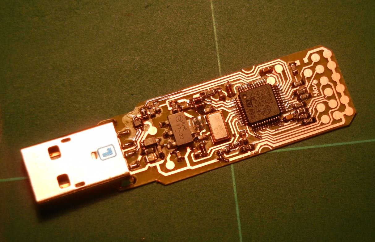
After placing all components, the PCB looks great. It took me one evening from bare FR4 to complete assembled module:
And finally…… I started nice little application called USBDevView and crossed my fingers:
Yeeaaahhh, the brain surgery was success.
I can now start debugging wit my little old/new miniature STLINK V2 USB dongle.
Thank you for reading this post!
Marko
Altium files can be requested via email.
Board looks great. How did you preserve 90 ohm USB differential pair on data ports with single sided PCB? And where will you get STLink V2 binaries? Is firmware publicly available?
For short lines it is not such a big deal. Maybe additional pair of few pF capactiors could help in case of trouble. So far I didn’t notice any trouble with similar designs.
About firmware: there are some clones of stlink “out there in the wild” based on OCD:
https://github.com/texane/stlink
https://sourceforge.net/p/openocd/code/ci/76afadeb7b4e428c1543b4f5218aa253bdd85e40/tree/src/jtag/drivers/stlink_usb.c
For start, the “shortcut” will be removing the STM32F103 from discovery board and placing it on this PCB. There’s nothing to loose.
Check the housing for this project:
http://e.pavlin.si/2016/02/24/housing-for-st-link-v2-on-a-single-sided-diy-pcb/
Here are instructions how to program blank STM32 with STLink firmware>>> http://e.pavlin.si/2016/02/28/how-to-program-blank-stm32f1-with-stlink-v2-firmware/
Hallo, can you send for me the board file for this Projekt? 🙂 Thanks, Adam