LED decoration
This LED decoration is for beginners in microcontroller applications. It has 8 LEDs, audio generator and possibility to interconnect with other modules. The PCB is simplified to certain level in order to be manufacturable on a single sided substrate with minimum effort. There are only two wire bridges and one 0 ohm resistor in addition to other components. The LED decoration can be used in school projects or for new-years fun. Of course it’s not limited to X-mas tree. It can be used during Bodhi Day, Hanukkah, Id al-Adha, Winter Solstice celebration, Saturnalia, Yule, Kwanza, Omisoka or any other occasion which might come at the end of the year, when day is short and some LED blinking device might rise your mood.
The concept of this LED decoration:
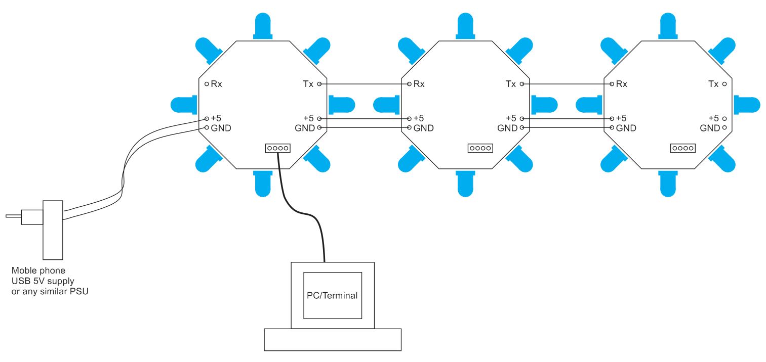
LED decoration concept
Each module has 20 pin STM32F0 microcontroller with USB and UART connection, low drop voltage regulator, 1W audio amplifier and 8 LEDs. The complete schematic diagram:

LED decoration schematic
Here is PDF version.
The PCB has 8 LEDs around:

LED decoration PCB with 8 LEDs
The 3D view shows how are LEDs placed. The speaker is mounted at the reverse side. It is important to know there is no need to assemble all components on all modules when they are connected in a chain. There is no need to play songs with all modules (although it could produce interesting sound effects).
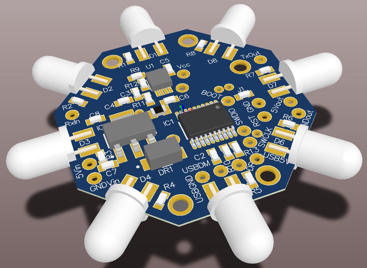
LED decoration – 3D view on PCB
As I mentioned, the PCB can be produced with “toner transfer” method or any other prototyping technology. Here are the necessary files: SINGLE PDF, 12-times PDF, GERBER.
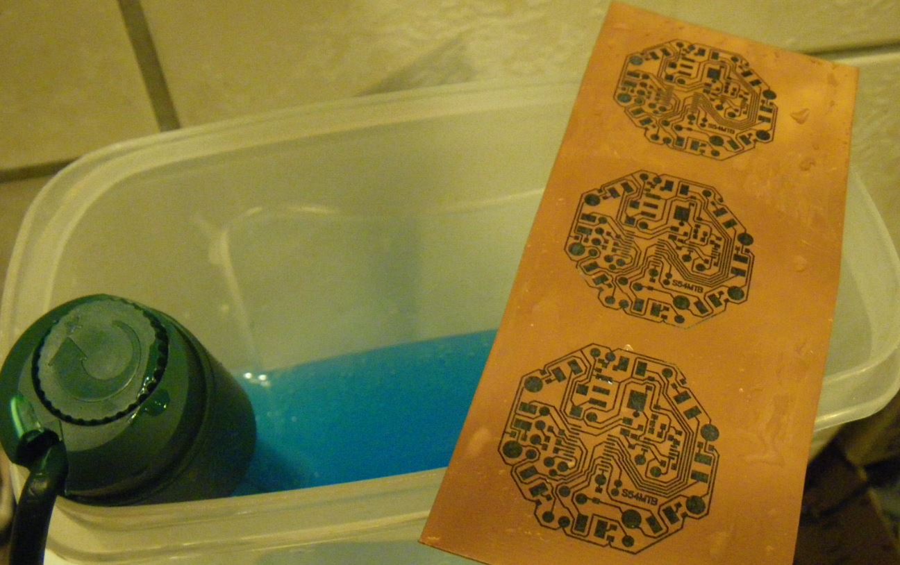
The first prototypes were etched:

Preparation for etching — transferring toner to the pcb
The toner has been transferred
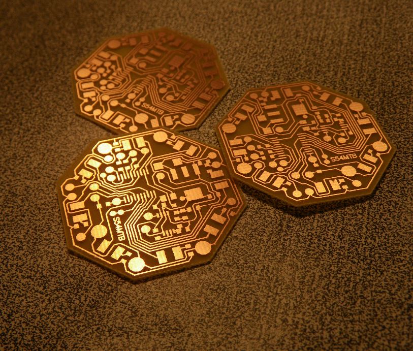
Etched PCBs
Now it’s time to prepare some serious quantity of LEDs:

1000 pcs of LEDs
Assembly of the module is simple. Just follow the assembly drawing and schematic. Here is complete documentation in a single PDF file.
Microcontroller port assignment:

GPIO Ports for LEDs
First three modules assembled and working:

First three prototypes assembled and running

One of the ideas was to place a straw on top of each LED
The software for this project is under development. Just follow this site for updates.
Update 04.dec.2016…..
Preliminary operation:
The “program” table content for demo above is:
/* __ __ __ __ __ __ __ | |_ | \ |__) |__) / \ / _ |__) /\ |\/| |__ |__ |__/ | | \ \__/ \__) | \ /--\ | | */ { CMD_FADE, 150 }, { CMD_VOL, 100 }, {CMD_LED, 0x01},N_E4,{CMD_MPAUSE,480}, {CMD_LED, 0x02},N_E4,{CMD_MPAUSE,320}, {CMD_LED, 0x04},N_E4,{CMD_MPAUSE,160}, {CMD_LED, 0x08},N_G4,{CMD_MPAUSE,640}, {CMD_LED, 0x10},N_REST,{CMD_MPAUSE,160}, {CMD_LED, 0x20},N_G4,{CMD_MPAUSE,160}, {CMD_LED, 0x40},N_A4,{CMD_MPAUSE,320}, {CMD_LED, 0x80},N_A4,{CMD_MPAUSE,160}, {CMD_LED, 0xff},N_F4,{CMD_MPAUSE,320}, {CMD_LED, 0x00},N_A4,{CMD_MPAUSE,160}, {CMD_LED, 0xff},N_C5,{CMD_MPAUSE,960}, {CMD_LED, 0x00},N_G4,{CMD_MPAUSE,320}, {CMD_LED, 0xff},N_G4,{CMD_MPAUSE,160}, {CMD_LED, 0x00},N_E4,{CMD_MPAUSE,320}, {CMD_LED, 0x01},N_D4,{CMD_MPAUSE,160}, {CMD_LED, 0x02},N_C4,{CMD_MPAUSE,480}, {CMD_LED, 0x03},N_E4,{CMD_MPAUSE,320}, {CMD_LED, 0x04},N_F4,{CMD_MPAUSE,160}, {CMD_LED, 0x06},N_G4,{CMD_MPAUSE,480}, {CMD_LED, 0x08},N_F4,{CMD_MPAUSE,320}, {CMD_LED, 0x0b},N_D4,{CMD_MPAUSE,160}, {CMD_LED, 0x10},N_C4,{CMD_MPAUSE,1920}, {CMD_LED, 0x20},N_E4,{CMD_MPAUSE,480}, {CMD_LED, 0x30},N_E4,{CMD_MPAUSE,320}, {CMD_LED, 0x40},N_G4,{CMD_MPAUSE,160}, {CMD_LED, 0x60},N_REST,{CMD_MPAUSE,640}, {CMD_LED, 0x80},N_G4,{CMD_MPAUSE,160}, {CMD_LED, 0xb0},N_A4,{CMD_MPAUSE,160}, {CMD_LED, 0x00},N_A4,{CMD_MPAUSE,320}, {CMD_LED, 0x01},N_F4,{CMD_MPAUSE,160}, {CMD_LED, 0x02},N_A4,{CMD_MPAUSE,320}, {CMD_LED, 0x04},N_C5,{CMD_MPAUSE,160}, {CMD_LED, 0x08},N_G4,{CMD_MPAUSE,960}, {CMD_LED, 0x10},N_G4,{CMD_MPAUSE,320}, {CMD_LED, 0x20},N_FS4,{CMD_MPAUSE,160}, {CMD_LED, 0x40},N_E4,{CMD_MPAUSE,320}, {CMD_LED, 0x80},N_B4,{CMD_MPAUSE,160}, {CMD_LED, 0xff},N_G4,{CMD_MPAUSE,480}, {CMD_LED, 0x00},N_A4,{CMD_MPAUSE,320}, {CMD_LED, 0xff},N_B4,{CMD_MPAUSE,160}, {CMD_LED, 0x00},N_C5,{CMD_MPAUSE,480}, {CMD_LED, 0xff},N_B4,{CMD_MPAUSE,320}, {CMD_LED, 0x00},N_E4,{CMD_MPAUSE,160}, {CMD_LED, 0x01},N_REST,{CMD_MPAUSE,1600}, {CMD_LED, 0x02},N_G4,{CMD_MPAUSE,160}, {CMD_LED, 0x03},N_G4,{CMD_MPAUSE,160}, {CMD_LED, 0x04},N_A4,{CMD_MPAUSE,480}, {CMD_LED, 0x06},N_D4,{CMD_MPAUSE,480}, {CMD_LED, 0x08},N_G4,{CMD_MPAUSE,480}, {CMD_LED, 0x0b},N_A4,{CMD_MPAUSE,480}, {CMD_LED, 0x10},N_G4,{CMD_MPAUSE,320}, {CMD_LED, 0x20},N_C5,{CMD_MPAUSE,160}, {CMD_LED, 0x30},N_E4,{CMD_MPAUSE,320}, {CMD_LED, 0x40},N_A4,{CMD_MPAUSE,160}, {CMD_LED, 0x60},N_G4,{CMD_MPAUSE,480}, {CMD_LED, 0x80},N_G4,{CMD_MPAUSE,320}, {CMD_LED, 0xb0},N_G4,{CMD_MPAUSE,160}, {CMD_LED, 0x00},N_A4,{CMD_MPAUSE,480}, {CMD_LED, 0x01},N_D4,{CMD_MPAUSE,480}, {CMD_LED, 0x02},N_G4,{CMD_MPAUSE,480}, {CMD_LED, 0x04},N_A4,{CMD_MPAUSE,480}, {CMD_LED, 0x08},N_G4,{CMD_MPAUSE,320}, {CMD_LED, 0x10},N_C5,{CMD_MPAUSE,160}, {CMD_LED, 0x20},N_E4,{CMD_MPAUSE,320}, {CMD_LED, 0x40},N_G4,{CMD_MPAUSE,160}, {CMD_LED, 0x80},N_C5,{CMD_MPAUSE,960}, {CMD_LED, 0xff},N_C5,{CMD_MPAUSE,960}, {CMD_LED, 0x00},N_B4,{CMD_MPAUSE,480}, {CMD_LED, 0xff},N_A4,{CMD_MPAUSE,320}, {CMD_LED, 0x00},N_B4,{CMD_MPAUSE,160}, {CMD_LED, 0xff},N_A4,{CMD_MPAUSE,960}, {CMD_LED, 0x00},N_REST,{CMD_MPAUSE,640}, {CMD_LED, 0x01},N_A4,{CMD_MPAUSE,160}, {CMD_LED, 0x02},N_D5,{CMD_MPAUSE,160}, {CMD_LED, 0x03},N_D5,{CMD_MPAUSE,960}, {CMD_LED, 0x04},N_A4,{CMD_MPAUSE,320}, {CMD_LED, 0x06},N_A4,{CMD_MPAUSE,160}, {CMD_LED, 0x08},N_A4,{CMD_MPAUSE,320}, {CMD_LED, 0x0b},N_C5,{CMD_MPAUSE,160}, {CMD_LED, 0x10},N_C5,{CMD_MPAUSE,960}, {CMD_LED, 0x20},N_REST,{CMD_MPAUSE,640}, {CMD_LED, 0x30},N_C5,{CMD_MPAUSE,160}, {CMD_LED, 0x40},N_E5,{CMD_MPAUSE,160}, {CMD_LED, 0x60},N_D5,{CMD_MPAUSE,960}, {CMD_LED, 0x80},N_D5,{CMD_MPAUSE,640}, {CMD_LED, 0xb0},N_G4,{CMD_MPAUSE,160}, {CMD_LED, 0x00},N_C5,{CMD_MPAUSE,160}, {CMD_LED, 0x01},N_C5,{CMD_MPAUSE,960}, {CMD_LED, 0x02},N_B4,{CMD_MPAUSE,480}, {CMD_LED, 0x04},N_A4,{CMD_MPAUSE,320}, {CMD_LED, 0x08},N_G4,{CMD_MPAUSE,160}, {CMD_LED, 0x10},N_G4,{CMD_MPAUSE,960}, {CMD_LED, 0x20},N_G4,{CMD_MPAUSE,320}, {CMD_LED, 0x40},N_A4,{CMD_MPAUSE,160}, {CMD_LED, 0x80},N_G4,{CMD_MPAUSE,320}, {CMD_LED, 0xff},N_G4,{CMD_MPAUSE,160}, {CMD_LED, 0x00},N_G4,{CMD_MPAUSE,960}, {CMD_LED, 0xff},N_C5,{CMD_MPAUSE,480}, {CMD_LED, 0x00},N_D5,{CMD_MPAUSE,480}, {CMD_LED, 0xff},N_D5,{CMD_MPAUSE,960}, {CMD_LED, 0x00},N_G4,{CMD_MPAUSE,480}, {CMD_LED, 0x01},N_E5,{CMD_MPAUSE,480}, {CMD_LED, 0x02},N_E5,{CMD_MPAUSE,960}, {CMD_LED, 0x03},N_D5,{CMD_MPAUSE,480}, {CMD_LED, 0x04},N_C5,{CMD_MPAUSE,480}, {CMD_LED, 0x06},N_B4,{CMD_MPAUSE,960}, {CMD_LED, 0x08},N_C5,{CMD_MPAUSE,480}, {CMD_LED, 0x0b},N_D5,{CMD_MPAUSE,320}, {CMD_LED, 0x10},N_C5,{CMD_MPAUSE,160}, { CMD_RESTART, 0}, |
Where “notes” are defined in this source file.
The “custom assembler” table has following fixed length structure:
typedef union { struct { uint16_t CMD :4; /* Command is 4 bits long */ uint16_t PAR :12; /* 12 bit parameter */ } f; uint16_t c; } LED_CMD_t; |
and the “commands” are:
#define CMD_LED 0x1 // set led #define CMD_SOUND 0x2 // play sound #define CMD_VOL 0x3 // sound volume #define CMD_MPAUSE 0x4 // pause in ms #define CMD_SPAUSE 0x5 // pause in 1/10 second unit #define CMD_FADE 0x6 // set LED fading rate #define CMD_REMOTE 0x7 // send remote command #define CMD_RESTART 0xf // end of program, restart |
Example to turn all LEDS on:
{CMD_LED, 0xff} |
Parameter for sound command CMD_SOUND is standard MIDI note number. The notes starts from third octave (C3), which is MIDI note number 24. The simple buzzer could not play lower than that.
The command CMD_VOL parameter is 1 to 100. The scale is not linear. Some experimenting is necessary to get proper volume.
Commands CMD_MPAUSE and CMD_SPAUSE are simply pause in execution of the program. The parameter is millisecond or one tenth of a second for longer pauses.
The “fading rate” controls the spped of transition between changes in LED state. When new LED combination is set, the transition may occur instantly with CMD_FADE set to 0. For longer transition times, the parameter is millisecond from 0 to 100% LED power.
Every program should finish with the CMD_RESTART. That is simply indication where program ends and should be repeated in loop.
Status overview…….
Operational so far:
- USB virtual com port with console line editor (for editing LED/sound programs)
- Timer handler for sound: PWM with programmable frequency for pitch and pulse width for volume
- LED PWM timer handler for dimming for slow transitions (command CMD_FADE)
- Timer for running sequences of commands from the table
- UART handler for communication between modules connected in series
ToDo list:
- remote communication (running “programs” via UART commands)
- Program editor
- Internal FLASH storage
How did you transferred toner so good? What paper did you use?
The paper is some kind of thin glossy paper. Same results are with catalogs from local stores. I tested also dextrin-coated paper from Fab-in-a-box kit. Laminator I use is some mid-range GBC office laminator at max. temperature settings.