Wakeboarding winch build log
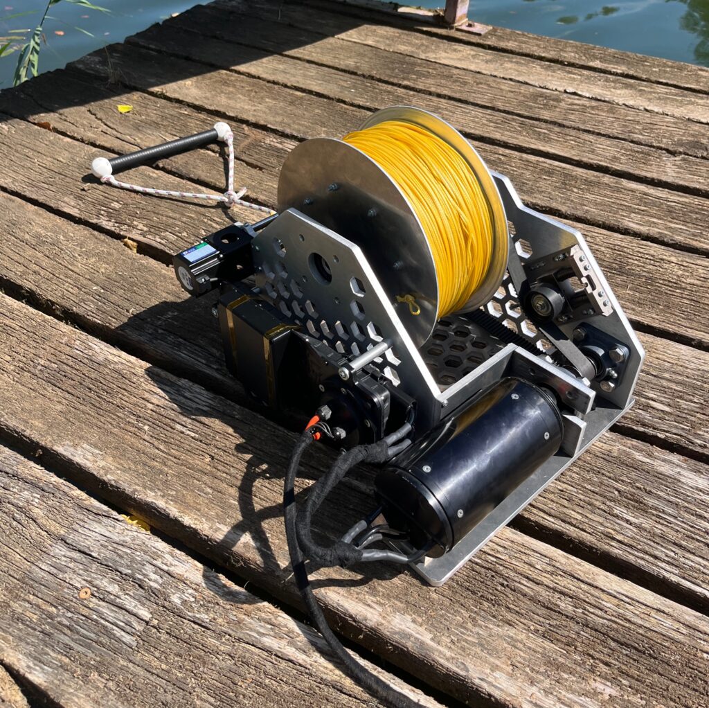
I built an electric drum winch for towing a wakeboarder. It is a personal project. The motor and the battery come from an Awake board, both rescued from scrap. Everything else is my own design: frame, drum, belt drive, rope guide, the rope guide electronics and the firmware.
| Item | Value |
|---|---|
| Design target | 40 km/h rope speed, 1000 N pull, about 10 kW |
| Motor | 12 kW Awake motor, VESC controller |
| Battery | 24S10P 18650 pack, LG HJ2 cells, about 100 V fully charged |
| Reduction | HTD 5M belt, 20T to 142T, 7.1:1 |
| Drum | 200 mm core, 300 mm flanges, 120 mm wide |
| Rope | 300 m Dyneema SK-75, 3 mm, 0.84 t breaking load |
| Rope guide | NEMA 23 stepper on a 12 mm ball screw, follows the VESC techo over CAN. |
| Cost | About 700 EUR, motor and battery from scrap |
Drum and frame
The drum core is 200 mm in diameter and 120 mm wide, 3D printed. The flanges are 300 mm in diameter and 6 mm thick, laser cut at Elba d.o.o. and then CNC finished at home workshop. The 20 mm axle was bought at a hardware store and turned by a friend to fit in the bearings. The axle runs in two UCF204 flange bearing units from 123bearing, 6.56 EUR each.
The dimensions come from a spool calculation. 400 m of 3 mm rope on a 200 mm core, 120 mm wide, is 13 layers at 100 % fill. With a fill factor of 0.8, which is typical for thin rope with many layers, it is 17 layers, or 50 mm of rope. That is exactly the 50 mm flange height. Bending is not the limit: Dyneema needs a bend ratio of 6 to 10, so a 30 mm drum would already be fine. In the end 300 m of rope was installed to save on cost. Dyneema rope is expensive!
The frame is 10 mm laser-cut plate, also from Elba d.o.o.. Side A is 470 x 260 mm, side B 350 x 260 mm, the bottom plate 470 x 390 mm. There is a pulley strut, a pulley side plate and a 240 x 75 mm rope guide mount. The hexagonal cutouts take weight out of the plates. The plates are aluminum. No strength calculations were done. Instead a very generous material thickness was selected which resulted in a very sturdy frame, but also a bit on the heavy side. This was a decision to get to the working unit faster.
Drivetrain
The motor is the 12 kW motor from an Awake board, driven by a motor controller based on VESC. The design targets were 40 km/h rope speed and 1000 N pull at the rider. With a mean spool circumference of 0.71 m, 40 km/h means 944 rpm at the drum. At 5700 rpm motor speed that gives a reduction of about 6:1, 100 Nm at the drum and 16.6 Nm at the motor. Required motor power comes out at 9.9 kW, so the 12 kW motor is just enough.
I used a 20-tooth HTD 5M pulley on the motor side and a 142-tooth pulley on the drum, so the reduction is 7.1:1. The small pulley is a stock part from Tehimpex, drilled to fit. The big pulley is 226 mm in diameter and 3D printed, with two 3D printed flanges. The belt is HTD 5M, 1035 mm long and 25 mm wide, also from Tehimpex. The ROBAJ15 tensioner (45.56 EUR) and the TPCFN45-25 idler (13.29 EUR) are from Misumi. The number of teeth on the big pulley is large and the load runs are short so the 3D printed pulley held well.
The motor does not sit on the belt shaft directly. It is coupled through a Misumi MJT-30K jaw coupling (43.84 EUR) to a 12 mm pulley shaft, which runs in two UCF201 flange bearings. The pulley shaft is a reused Awake drivetrain shaft.
With the 142-tooth pulley gives about 39 km/h rope speed at 6500 rpm and about 1170 N constant pull on an empty drum, with 1.5x that for short bursts. A 25 mm belt is on the thin side for this power. A belt width of 35 to 40 mm would be more buitable for 8 kW with intermittent duty. However for limited amount and short runs it has held up pretty good.
Battery and rope
The battery is the same pack as it is used in the Awake system: 24S10P of LG HJ2 18650 cells, about 100 V fully charged. The VESC and the rope guide board both run from it directly. There is no separate low-voltage supply.
The rope is 3 mm Dyneema SK-75 from syntheticropes.eu at 0.87 EUR per meter. The calculation was done for 400 m, I ordered 300 m. It cost 271.33 EUR plus 28.89 EUR delivery, 300.22 EUR in total. Breaking load is 0.84 t.
Rope guide
300 m of 3 mm rope is 13 to 17 layers on the drum. Without a level wind the rope piles up in the middle and digs into the layers below under load. So the winch has a motorized rope guide that moves across the drum as it turns.
Now would using a larger drum with fewer layers achieve the same thing? Most likely. But this is a home project and over-engineering is allowed!
The numbers: at 40 km/h the drum turns 15.7 times per second, so the guide has to move 47 mm/s. I sized it for a 1000 N side load, for the case where the rope comes in at an angle. With a 4 mm lead ball screw at 85 % efficiency that is 0.75 Nm and 708 rpm at the screw, about 55 W. The motor torque only depends on the side force. The motor speed scales with drum speed.
The build: an SFU1204 ball screw (12 mm, 4 mm lead, 250 mm) from Aliexpress, driven by a NEMA 23 stepper (57 x 56 mm, 8 mm shaft) through a D20L25 flexible coupling. The screw runs in a 608 and a 6000 bearing, held in CNC-milled side mounts from JLC. The carriage body is 3D printed and slides on two 12 mm steel rods with linear bearings. The rope runs between eight MR83 ball bearings on 3 mm dowel pins, held in two 3D printed caps, so it rolls instead of rubbing. Two end switches (HD110V01A12AR) on 3D printed mounts are used for homing. The whole guide sits on the rope guide mount plate.
Rope guide driver board
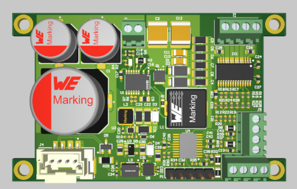
The stepper needs a driver, the driver needs CAN to talk to the VESC, and everything has to run from 100 V. I designed a board for this in Altium, a 4-layer PCB with:
- STM32F042F6P6 microcontroller, Cortex-M0, 32 kB flash, TSSOP20
- DRV8452 stepper driver, 50 V, 5 A, dual H-bridge, with stall detection
- TJA1051 CAN transceiver with PESD2CAN ESD protection
- LTC3894 step-down controller rated for 150 V input, with a 150 V P-channel MOSFET (SI7315DN) and 170 V Schottky diodes, 47 uH inductor, switching at about 106 kHz
- AP62300 buck and MIC5365 LDO for the 5 V and 3.3 V logic rails
- 470 uF 63 V and 2 x 33 uF 160 V bulk capacitors, 2.2 uF 250 V ceramics on the input
- Connectors for the stepper, the two end switches, an encoder input, CAN and a 5-pin SWD header
The LTC3894 steps the battery voltage down to the stepper supply. The first version ran at 36 V, which was too low, the guide motor did not reach the required speed. I changed the feedback resistors (R4 to 8.06 kOhm, R1 to 10 kOhm) and it now runs at 48 V with a 4 A limit.
I also designed a small encoder board with two DRV5015 Hall-effect latches, giving quadrature A/B outputs for a drum encoder. This would be used in case the sensorless tacho from VESC wouldn’t be accurate enough. In the end the firmware uses the VESC tachometer instead, so the encoder input on the driver board is unused for now.
Firmware
The firmware is plain STM32 HAL code. There is no user interface and nothing to configure. The board does one thing.
At power-up the stepper drives the carriage toward the end switch, zeroes the position and moves to the 20 mm start offset. Then it waits for CAN messages.
The VESC broadcasts status message 5 on the CAN bus at 250 kbit/s. It carries the motor tachometer value. On every message the board calculates how far the drum turned since the last one and moves the carriage by the matching fraction of the rope diameter: one full drum turn moves the guide by 3 mm. When the carriage reaches the end of the 120 mm spool width, the direction flips and the overshoot is carried over into the other direction. The guide does not care about rope speed, it just follows the drum.
Step pulses come from a timer interrupt at about 50 kHz with a trapezoidal motion profile: 2,000,000 steps/s² acceleration and 45,000 steps/s top speed. The stepper runs at 4x microstepping, which with a 4 mm lead is 200 steps per mm. The required 47 mm/s is 9,400 steps/s. I started with 16x microstepping, but the drum was too fast for that step rate, so I reduced it.
What went wrong
Three things from the prototype log:
- Rope guide driver, input voltage. 36 V on the stepper rail was too low and the guide motor did not reach the required speed. Fixed by raising the buck output to 48 V and the current limit to 4 A.
- Rope guide driver, heat. The DRV8452 overheated. More vias under the IC and a lower drive current. R18 was changed to 30 kOhm to reduce the full-scale current.
- Firmware, step rate. The drum was too fast for 16x microstepping. Reduced microstepping, now 4x.
- The sensorless motor startup had to be re-tuned for a load with a higher inertia than the propeller of the Awake board.
- Big pulley not being 100% correct scale due to 3D printing shrinkage. It made the belt skip at heavy load. 3D print would need to be dialed in or manufactured using water jet and aluminum.
Timeline and cost
- October 2024: winch CAD, production drawings for the laser-cut parts
- January 2025: rope guide CAD, driver PCB, encoder board
- March 2025: firmware
- August 2025: first run on the water
The whole build cost about 700 EUR. The rope is the biggest item at 300 EUR. The Misumi parts (coupling, idler, tensioner) are 103 EUR, the four flange bearings 26 EUR, the fairlead 18 EUR. The rest is laser cutting, CNC milling, PCBs, the stepper, the ball screw and small parts. The motor and the battery were rescued from scrap, so they cost nothing.
Water testing
https://youtube.com/shorts/Adb0Hk1ToHA
Or.. you can simply go to a wake park. But they you are riding in circles and where is the fun in that?


