Keyboard for a CNC – recycling a programmable keyboard

Final look
This keyboard is more than 10 years old. I got it for free but it had its problems. First one was a PS/2 interface. Not ideal for a keyboard used in 2016. Second problem was software for programming this keyboard. It came on not one, but two diskettes with DOS and Windows versions of the software.
That’s where I decided to take it apart and replace electronics inside. New controller is based on KeyWarrior IC which is capable of scanning 16×8 matrix.
This keyboard merges a standard keyboard with a jog controller for a CNC machine. Upper half are “normal” keys and bottom half is for controlling my CNC machine. The shortcut keys will save me a lot of time and trouble when working with the machine.
Keyboard’s original software came on two diskettes with software for DOS and windows

Two diskettes containing software
Switches are made by Cherry Americas. They are mounted using face plate mount technique. Each keycap has another cap made from clear plastic. A key label goes between those two caps.
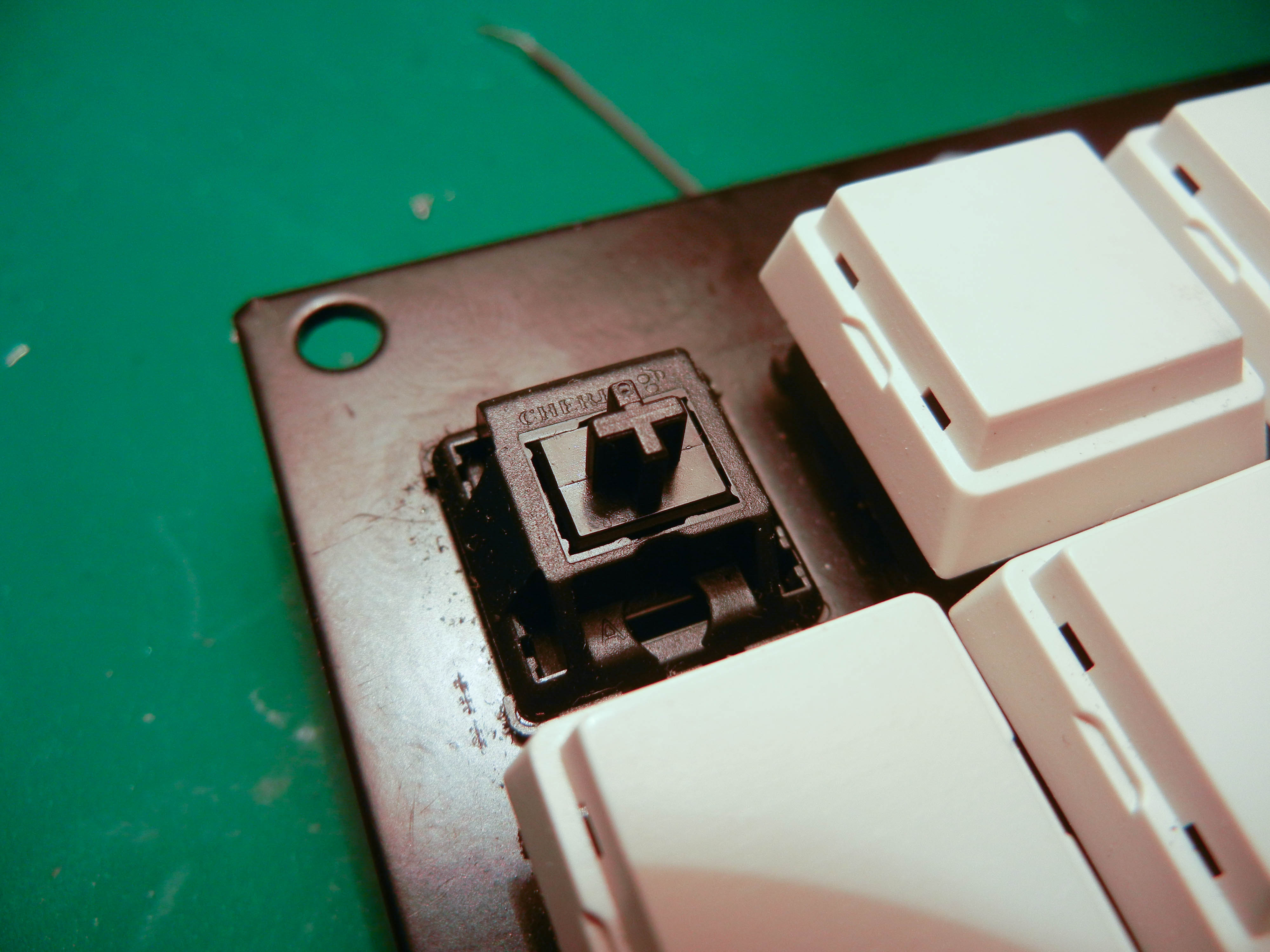
Switch made by Cherry Americas
Changing electronics
When I first opened it I was surprised how the matrix is arranged. It was done so to prevent phantom keys without using diodes. Board had one Motorola microcontroller and two 1/8 multiplexers. horizontal lines of the matrix were connected directly to the Motorola chip while other twelve went through two multiplexers to get the number of required inputs down.

Main board of the keyboard
My USB keyboard controller
It is based on a KeyWarrior IC with external EEPROM for storing key tables. Device requires 6 MHz crystal to operate (6 MHz / 4 = 1.5 MHz). TVS diode array on USB protects the device from potential electrostatic discharges and other inconveniences that could occur on the USB lines. Additional PNP transistors extend the maximum current of lock key indicators so it is suitable for driving more powerful LEDs. Matrix connectors are placed on sides.

KeyWarrior based USB controller
Gerbers and design files are available here: http://gal.pavlin.si/key/keyboard-controller.zip
Here’s my keyboard controller mounted where the old one used to be. Mount was made with a piece of PMMA plastic.

My USB controller
I like devices to have connectors instead of fixed cables because it makes them more practical. My controller has standard mini USB connector that is commonly found in cameras.

Mini USB connector
It wasn’t difficult to find which pins belong to matrix. All I had to do was open the datasheet of the multiplexer and check which pins are inputs. Finding the horizontal 8 was even easier because they all had 10 kOhm pulldown resistors.

All wired to the board
It all worked perfectly.
Key labels
Next thing I did was print key labels. I still had to figure out the most suitable layout of the keys so some experimenting was present. It took me a good hour.
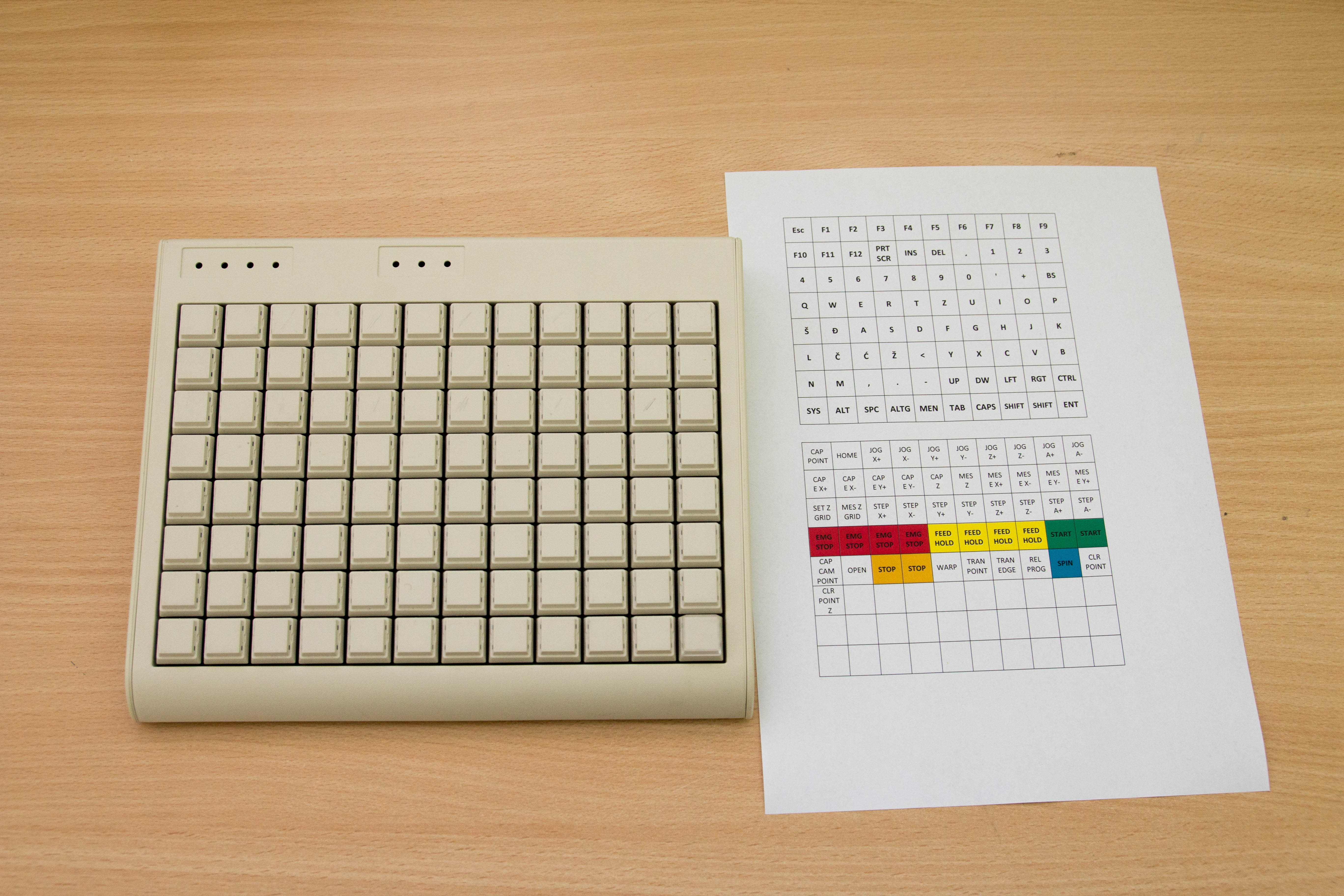
Keyboard with key labels next to it
Key mapping
Key mapping is done via USB and it’s rather simple and straightforward. Chip I used supports 31 character long macros for each key on 3 levels. This means you can easily map “www.” or “.com” on a single key.

Table Editor
It took some time to figure out the matrix because it had no visible succession.
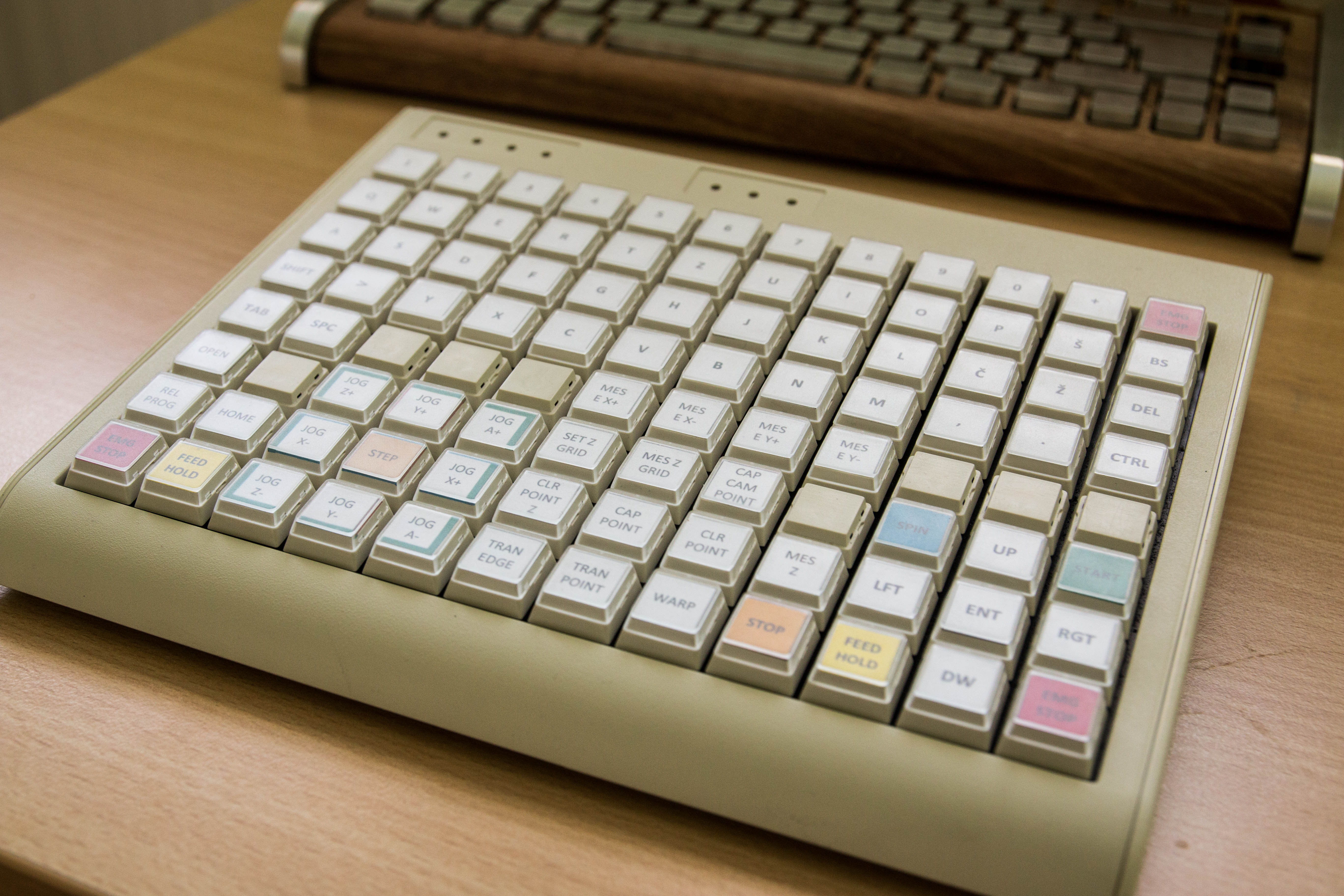
Keyboard ready to serve its purpose
I hope I won’t have to use the red corner buttons too much. They are emergency stop keys.
Programmable and relegendable, that’s a handy board to have around! Good work 🙂