Soldering TQFN with a distance
The MCBs (Machined Circuit Boards – an alternative to DIY printed circuit boards) are now jumping out from the mini-CNC like in high volume production. This is new revision of RH/Temperature sensor with RS485 interface with Si7013:

New revision of Si7013 sensor module – machined boards
The boards are solder “plated” and prepared for assembly process. However, there is one issue with Si7013. It comes in SMD housing without leads. This is no big trouble, but the thermal pad is, because there is trace routed under the Si7013, which is not GND:
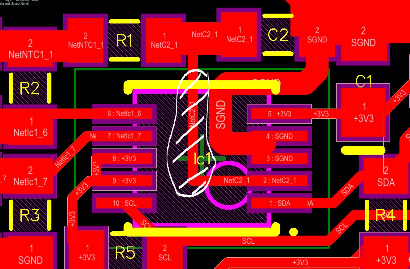
The “problematic” trace is white hatched.
That means it must not be soldered to thermal pad. The good thing is, the thermal pad can be left floating.
I will skip the MCB preparation process. It is described elsewhere:
The closeup of the Si7013 PCB looks like this:
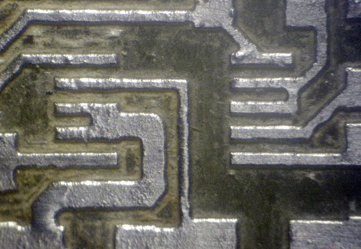
Closeup of the pads
Here is my solution to this problem. First clamp the Ic to vise or ask your wife to hold the tweezers with the chip:

Holding the Si7013 in position – ready for soldering pads
Next, use your sharpest soldering tip and apply some solder to the pads. Please keep in mind the chip has 0,5mm raster between pads.

Chip with soldered pads
After soldering all 10 pads it should look something like this:
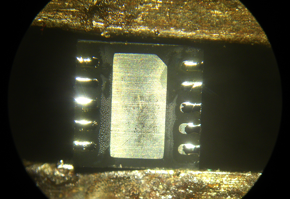
All pads soldered
Now place the chip on the PCB and position it correctly – check the orientation. The height of the solder applied to the chip pad will keep the thermal pad away from the traces under the chip. Place soldering tip close to the chip at one pad and heat it up until solder flows from chip to the PCB pad. Don’t push the chip down! Check the position of the chip and repeat this for all pads at one side and then repeat for the rest of the pads:
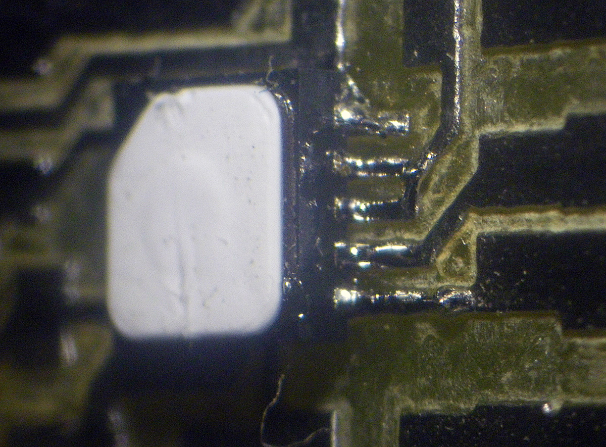
Place on PCB and heat the pads on circuit board.
At the end, check for the shorts. Only the pads 3 and 4 are GND, pad2 should be connected to R1/C2 and pads 8,9 are both connected to the 3.3V (check the schematic or layout above). If everything goes well, congratulate yourself for successful manual soldering. There is no pick and place machine, which can do something like that!

At the end, check for shorts. Repeat the process if necessary