Low cost single cell battery pack simulator
Modern battery operated portable devices use smart battery packs. Every new development of an electronic medical device must follow strict design flow defined by world-wide or local regulatory
directives. The development process of any such device using smart battery pack requires specific operating conditions to meet the testing criteria. When smart battery pack is one of the main power sources the host system should be tested with several battery states. The testing is necessary during development, validation and later in production testing.

Battery simulator block diagram
Testing process
During development cycle test specifications and pass criteria must be provided base on the product specification. Production test also could be treated as a simplified qualification test, because it has to follow several standard regulations. Efficient production cycle for every product has time constraints on each station. The target of production test is deliver quality products, but it could not go through all engineering details and should be finished within limited time.
Battery cell
There are several problems when using real battery cells for such tasks:
- limited charge and discharge rates,
- limited battery cell charge cycles,
- charge maintenance,
Every battery cell has maximum charge and discharge rates, which must not be exceeded to avoid risks of battery damage, overheating and fire. Charge and discharge rates then limit shortest possible times to set the battery cell to defined state within charge and discharge cycle. As it could have limited usability for development, long testing times are not acceptable for production process and should be avoided.
Next problem with cycling real battery cells is limited number of charge/discharge cycles. Good lithium cell could have about 1000 charge cycles, which is too low for serious production.
And finally, every battery cell needs some maintenance when not in use to keep it in shape and within expected specifications.
Battery fuel gauge
The battery cell usefulness is hampered by the fact that it cannot communicate with the hosting system. Battery gauge is used for capacity monitoring and reporting. The device monitors a charge and discharge activity of the battery cell and provides available time-to-empty information across a wide range of operating conditions. It communicates to the system over a HDQ one-wire or I2C serial interface. Internal registers are updated with battery cell activity and they have no possibility to set user-predefined values. This makes standard fuel gauge devices useless in testing systems.
Smart battery pack emulator
There are many battery cell simulators available which could simulate battery cell(s). Unfortunately, none is emulating any of the digital protocols used by fuel gauge devices. Optimal solution to efficiently emulate given smart battery pack is to use custom solution based on battery cell simulator and fuel gauge protocol emulator. Both parts could be fused together in small, but efficient smart battery pack emulator.
Presented solution will solve following problems associated with smart battery pack emulation:
- complete battery cell simulation
- fast response time
- unlimited cycle use
- flexible fuel gauge protocol emulation
- use of a standard interface for integration in automated test equipment
Typical requirements
Battery simulator should be capable of sourcing and sinking up to 2A currents, has digital interface for fuel gauge emulation and PC interface for controlling the simulator. It has two ports; one is application port, which consists of two power pads and digital interface for simulating one- or two-wire digital interface. The second is host port, which is one of the standard PC interfaces. The firmware should emulate the battery during charge and discharge states, and provide current and voltage measurements to the host.
Implementation
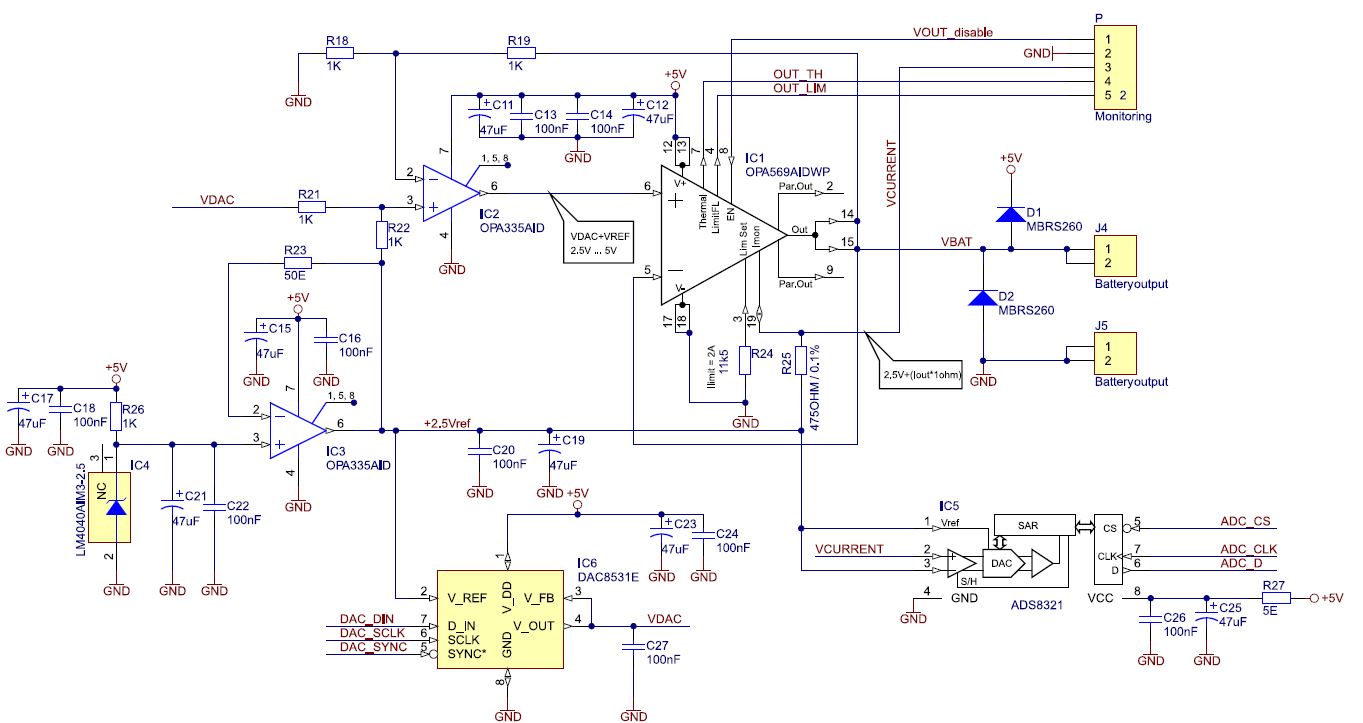
Basically, the implementation is typical four quadrant programmable voltage source. Output voltage is set by DAC. Heart of the analogue part of the circuit is power amplifier OPA569. It is a high-current, operational amplifier, which has output swing within 150mV of the supply rails at output current of 2A. It’s ideal component for the application. It has current limit that is set with an external resistor. The IMONITOR pin provides a bidirectional copy of the output current, which eliminates the need for a series current shunt resistor.
Detailed schematic is shown in Fig. 1. Control voltage is supplied from DAC (VDAC), which has output voltage from 0 to Vref. Reference voltage is 2,5V and it is added to DAC output voltage. Sum of both voltages has range from 2,5V to 5V, which cover complete battery cell voltage range. Output current is monitored at Imon pin. The current from Imon pin is 1/475 of output current. By adding 575 ohm resistor connected to 2,5V reference level, the current monitoring voltage is then:
Vcurrent = Vref + (Iout * 1 ohm)
With current limit set to 2A, the current monitoring voltage has range from 0,5 to 4,5V. his voltage is connected to ADC.

Fig.1 – Output stage implementation (not all decoupling shown)
The circuit at Fig. 1 requires one DAC to program the output voltage and one ADC to monitor the output current.
Digital part
Digital part of the circuit is built around LPC2148, which is ARM7 core microcontroller featuring USB device controller and other standard periphery. To avoid the need for special drivers or other installation, standard communication device class was used to emulate serial port communication via USB port. Several commands were implemented to control battery emulator.
The circuit was designed and assembled on a single 100x50mm board (Fig. 2). It has USB connection, power supply connector and three emulator pins: one analogue output, one digital communication input/output and common ground.

Fig. 2 – 100mmx50mm PCB for battery emulator
Schematic diagram
Only output stage with ADC
and DAC interfaces shown. The digital interface is implemented with LPC2148 microcontroller
Digital interface
Digital part of the circuit is built around ARM7 microcontroller LPC2148 featuring USB device controller and other standard periphery. To avoid the need for special drivers or other installation, standard communication device class was used to emulate serial port communication via USB port. Several commands were implemented to control battery emulator.

Digital interface schematic diagram
Altium files can be requested via email.
Software
Firmware for the battery simulator is based on virrtual com port (CDC device). Commands are sent to the device as string terminated with <CR>. There are several command groups. All commands are listed below:
| HLP | Print help | |
| SID | <id> | Set ID (id = 0…16777215) |
| GID | Print current ID | |
| SETREG | <addr> <val> | Set register at address <addr> to value <val> |
| SR | Same as SETREG | |
| GETREG | <addr> | Get register at address <addr> |
| GR | Same as GETREG | |
| EEPROM Registers | ||
| TCOMP | [<val>] | Temperature Compensation Constants |
| DCOMP | [<val>] | Discharge Rate Compensation Constants |
| IMLC | [<val>] | Initial Max Load Current |
| PKCFG | [<val>] | Pack Configuration Values |
| TAPER | [<val>] | Aging Estimate Enable, Charge Termination Taper Current |
| DMFSD | [<val>] | Digital Magnitude Filter and Self-Discharge Rate Constants |
| ISLC | [<val>] | Initial Standby Load Current |
| SEDV1 | [<val>] | Scaled EDV1 Threshold |
| SEDVF | [<val>] | Scaled EDVF Threshold |
| ILMD | [<val>] | Initial Last Measured Discharge High Byte |
| EE_EN | [<val>] | EEPROM Program Enable |
| RAM Registers | ||
| CSOC | [<val>] | Compensated State-of-Charge |
| CYCT | [<val>] | Cycle Count Total High – Low Byte |
| CYCL | [<val>] | Cycle Count Since Learning Cycle High – Low Byte |
| TTECP | [<val>] | Time-to-Empty At Constant Power High – Low Byte |
| AP | [<val>] | Average Power High – Low Byte |
| SAE | [<val>] | Available Energy High – Low Byte |
| MLTTE | [<val>] | Max Load Time-to-Empty High – Low Byte |
| MLI | [<val>] | Max Load Current High – Low Byte |
| STTE | [<val>] | Standby Time-to-Empty High – Low Byte |
| SI | [<val>] | Standby Current High – Low Byte |
| TTF | [<val>] | Time-to-Full High – Low Byte |
| TTE | [<val>] | Time-to-Empty High – Low Byte |
| AI | [<val>] | Average Current High – Low Byte |
| LMD | [<val>] | Last Measured Discharge High – Low Byte |
| CACT | [<val>] | Temperature Compensated CACD High – Low Byte |
| CACD | [<val>] | Discharge Compensated NAC High – Low Byte |
| NAC | [<val>] | Nominal Available Capacity High – Low Byte |
| RSOC | [<val>] | Relative State-of-Charge |
| FLAGS | [<val>] | Status Flags |
| VOLT | [<val>] | Reported Voltage High – Low Byte |
| TEMP | [<val>] | Reported Temperature High – Low Byte |
| ARTTE | [<val>] | At-Rate Time-to-Empty High – Low Byte |
| AR | [<val>] | At-Rate High – Low Byte |
| MODE | [<val>] | Device Mode Register |
| CTRL | [<val>] | Device Control Register |
| Cell generator commands | ||
| VOLTAGE | [<val>] | output voltage |
| V | [<val>] | Same as VOLTAGE |
| CURRENT | Get output current | |
| I | Same as CURRENT | |
| POWER | Get current power (Vout*Iout) | |
| MONITOR | <1/0> | Turn on/off HDQ monitor |
Source code with KEIL project is available here.
Precompiled HEX file is available here.