Radar under 20€ using cheap CDM324 24GHz doppler module
You can get CDM324 module on ebay for about 6€. It is constantly transmitting and receiving at 24GHz. It’s output is the difference between transmitted and received signal frequency.
I made a simple PCB with opamp, analog comparator and a powerful MCU STM32F4. Besides that, there are some other peripheral components. The PCB connects to the module with 3pin header. On the PCB, another PCB with small joystick is soldered. This joystick is used to interact with GUI on 128×64 graphic OLED display. The main PCB also has USB connector for virtual COM port and charging of 240mAh lithium battery.

Render of the device
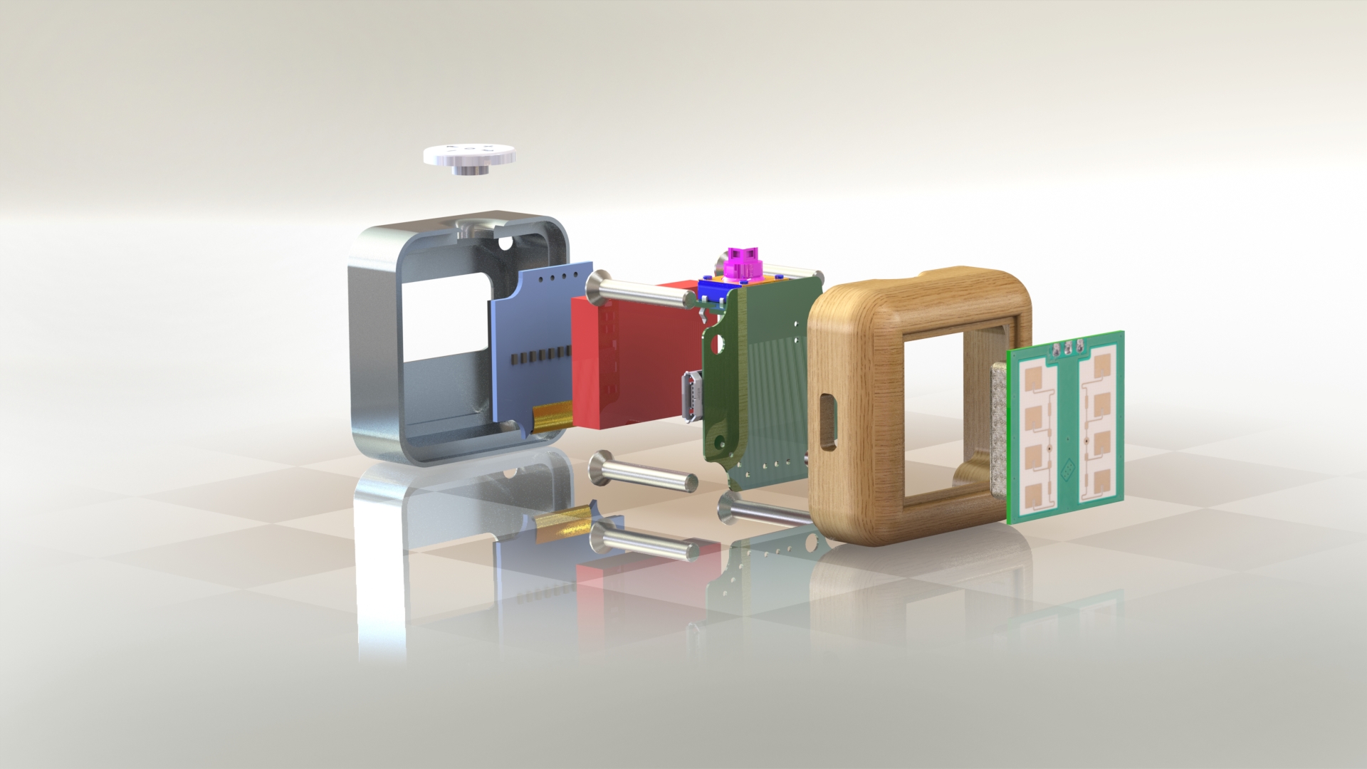
Exploded view of the whole device
About electronics and software
The output of the CDM324 module has very low level (100mV peak to peak at best) so it has to be amplified. For that I used the OP amp circuit found in this post. The output signal after the amplifier is somewhere at 3.3V level if the reflection is strong.
At first, I tried using an analog comparator to convert analog signal (sine wave) to digital pulses. When the input signal was lower than 3.3/2 V the comparator would output 0, and in the other case 3.3V. The real chalange came when I tried to sample those pulses. I tried using timer, with some filtering but couldn’t get any reliable information about the speed. The problem was that I was trying to analyse the frequency in time domain with many reflected signals interfering with each other. I didn’t play around with it too much, because I knew in the begging this wasn’t the best option to sample the doppler signal.
I also connected the output of the amplifier to a ADC input of the microcontroller. STM32F4 was used because it has FPU co-processor and DSP instructions. This means that FFT (time to frequency domain transformation) can be calculated accurately and in timely fashion. I found FFT libraries on this site and using them was straight forward. With some testing 20kHz sample rate and 1024 FFT size was determined to be enough. Converted to actual speed this means it can sample any object moving between 0 and 35 m/s.
I coded a simple GUI for OLED display that shows FFT graph and speed calculated from the frequency with peak amplitude. User can choose between two measuring ranges – 0-7 m/s and 6-35 m/s using the joystick on the top of the device. User can also zoom in and out on the graph using the joystick. Speed reading is displayed with big font and updates only about 3 times per second to get readouts easily. The graph however, is fluid and updated with 25Hz. The device is powered up by pressing the joystick’s center. To power down the user has to hold the joystick down for about 1 second. Pushing the joystick down briefly during normal operation enters the menu where user can adjust some parameters. The battery lasts for about 2 hours of operation.
Schematics can be found here.

PCB with CDM324 module underneath
Once I’ll be satisfied with end results I’ll also upload gerbers, software and 3D model files.
The hosing consist of three parts. The front wooden part, the back aluminum part and they joystick button which I machined with my CNC. All of those parts can be 3d printed as well. The button is glued on the joystick. The back and front part are screwed together with 4 kniping screws.
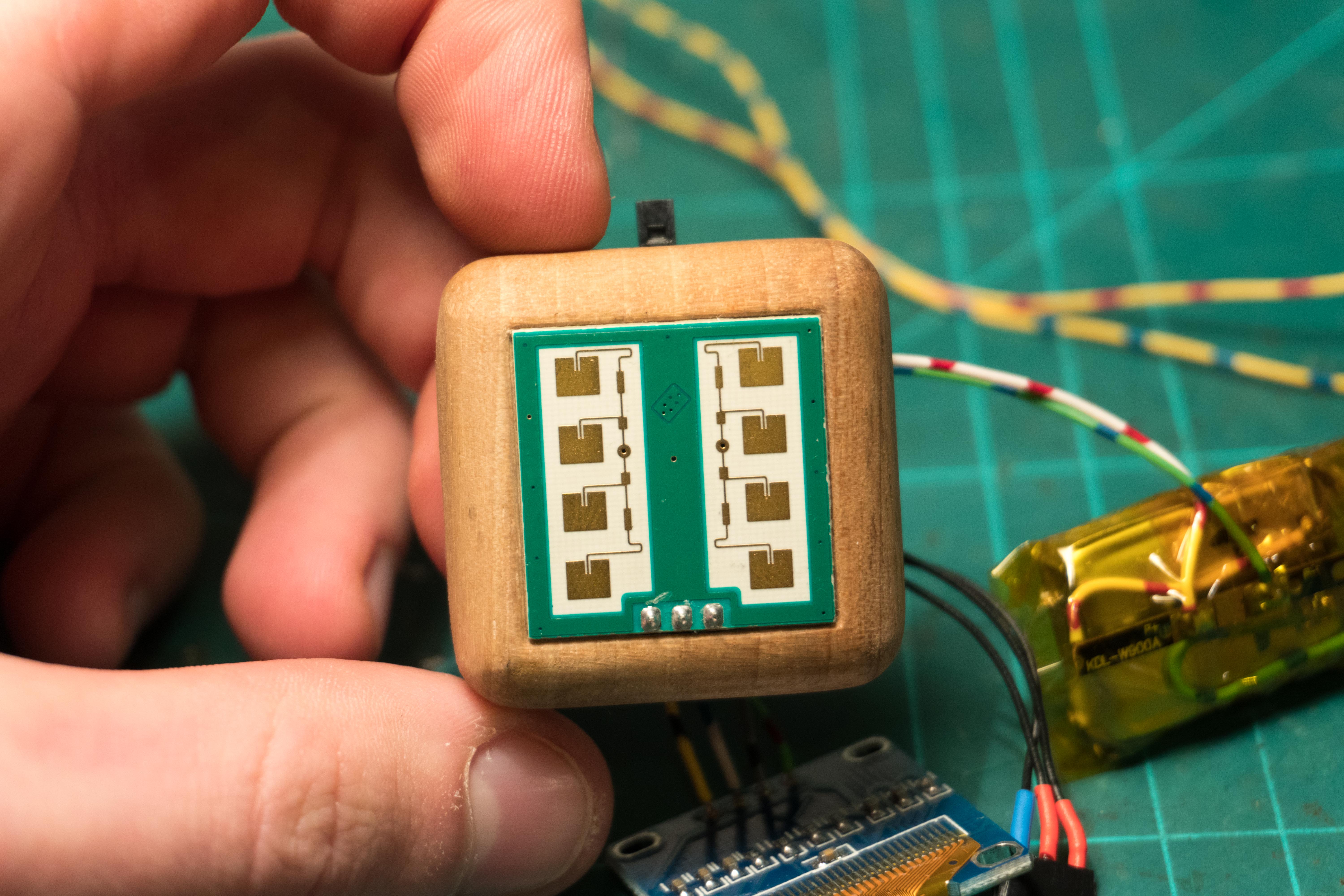
Front side of the device
Video of the device in action:
The radar can measure speed of an average human at range up to 5m and a car with range up to 20m. The bigger the target the stronger the reflection. One of the biggest problems with this module for any serious work is that it’s beam is too wide. The antenna would have to be at least twice the size.
Nice to see such a nice module!
Glad my schematics helped!