Collinear antenna for 868MHz Lorawan Gateway
This is description of coaxial collinear antenna for 868MHz applications. I designed this for Lorawan gateway.
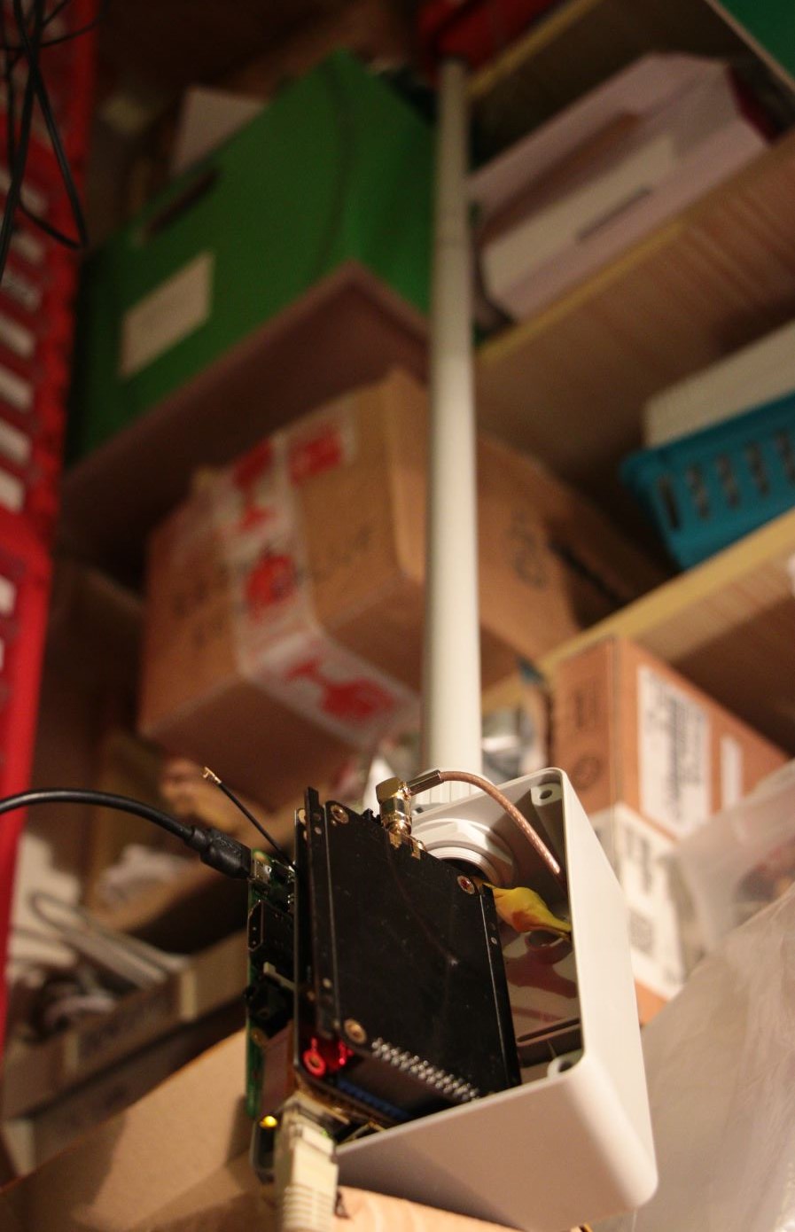
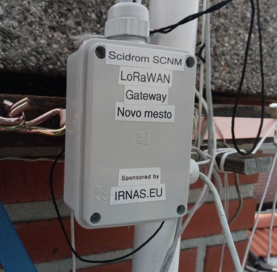
Antenna tested with lorawan gateway
Construction, materials and tools needed
The antenna is made of coaxial cable sections. It doesn’t have to be 50 Ohm coaxial cable, 75ohm for satellite TV will work as well. What is important, is the velocity factor of the coaxial cable. If the cable is unknown it’s fairly simple to measure the VF with some TDR method described elsewhere (one good example). I used commonly available RG58C/U with VF of 0,66. My local shop for electrical parts sells cables from italian producer Prospecta.
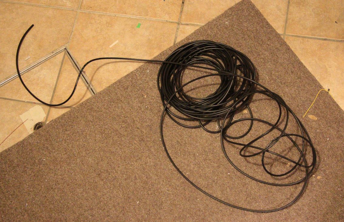
RG58-C/U
To feed the antenna some quality cable is needed with low loss at UHF frequencies. Good choice is RG316 or similar smaller diameter. Due to construction of the feed it is good coice to match the diameter of the internal dielectric in antenna coaxial cable segments to the diameter of the feed cable. I will describe this later.

Detail of the antenna feed
Further some connector is needed to match the LoRaWAN treansciever connector. Avoid adapters, because every adapter adds up to few dB of loss in signal. dB her and dB there seems not much, but remember 3dB means half of the signal.
This antenna is intended for LoRaWAN gateway for outdoor installation. This measns it will be exposed to the weather. I decided to place the antenna inside the plastic tube and mount it with the cable gland to the plastic housing, which can accomodate the LoRaWAN gateway with IP67 protection.

Housing and cable gland

Some must-have, other good-to-have tools
The tools needed for making this antenna are nothing special. The caliper or some precise measuring tape is a must-have. Antenna construction requires some soldering and cable cutting. Good-to-have is cable-peeling tool (marked with an arrow above), but it can be done with a sharp knife, too. The hot glue gun is useful for sealing this antenna and finally, if chosen connector requires crimping, some tool for connector assmbly is reqired. The ohm-meter would be also helpfull to check the shorts.
Calculation
Let’s start with some basic calculation. For this antenna we need half-wavelength in the coaxial cable. The wavelength of the signal is ![]()
For described antenna at f=868MHz, the wavelength in free space is: λ=345,6mm.
The electromagnetic waves in the coaxial cable propagate slower than in free air. The length L of the basic antenna element is the half wave length reduced by the velocity factor of the coaxial cable.  The length of the antenna sections made with cable RG58-C/U (VF=0,66) are 114mm long.
Construction
Start with even number of coaxial sections (more sections, more gain, sharper radiation pattern – recommended 4 or 6):
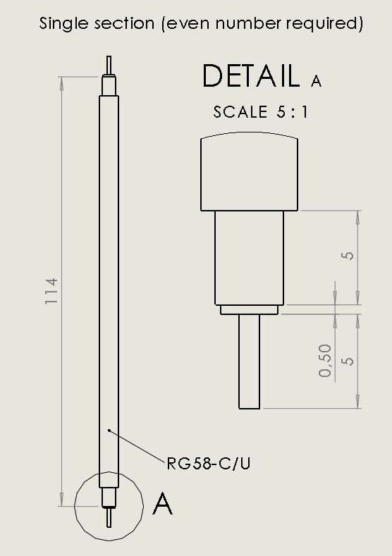
Single coaxial section
Measure the length of the coax shield to λ/2, add about 0,5mm of the internal dielectric and leave about 5mm of central conductor at each end of the cable. For RG58 this result in 125mm. Use sharp knife or cable peeling tool to open each end of the cable as shown in the drawing above. Cable preparation should look like this:
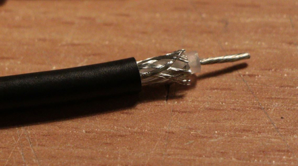
Cable ends preparation
When all cable sections are prepared, soder them together in a chain: the outer shield and inner conductors are counterchanged between two adjacent elements:

Connection between sections
Sections soldered together
Add copper wire λ/4 long at the one end of this chain. Length is 86mm (there is no coax, calculate the λ is in free space).

Final section of the antenna is λ/4

Solder this to the central conductor of the coax
Now prepare the antenna feed. It is constructed from RFI part and feed coaxial cable with connector. First, attach SMA connector to one end of the RG316. Then prepare the EMI part. Cut piece of RG58, with 58mm of the shield and add few mm at one end:

RFI shield
Pull out the cable dielectric and central conductor very carefully. Only shield and outer insulation should remain in one piece:

Preparation of the RFI part
and pull this over the RG316:

RFI skirt
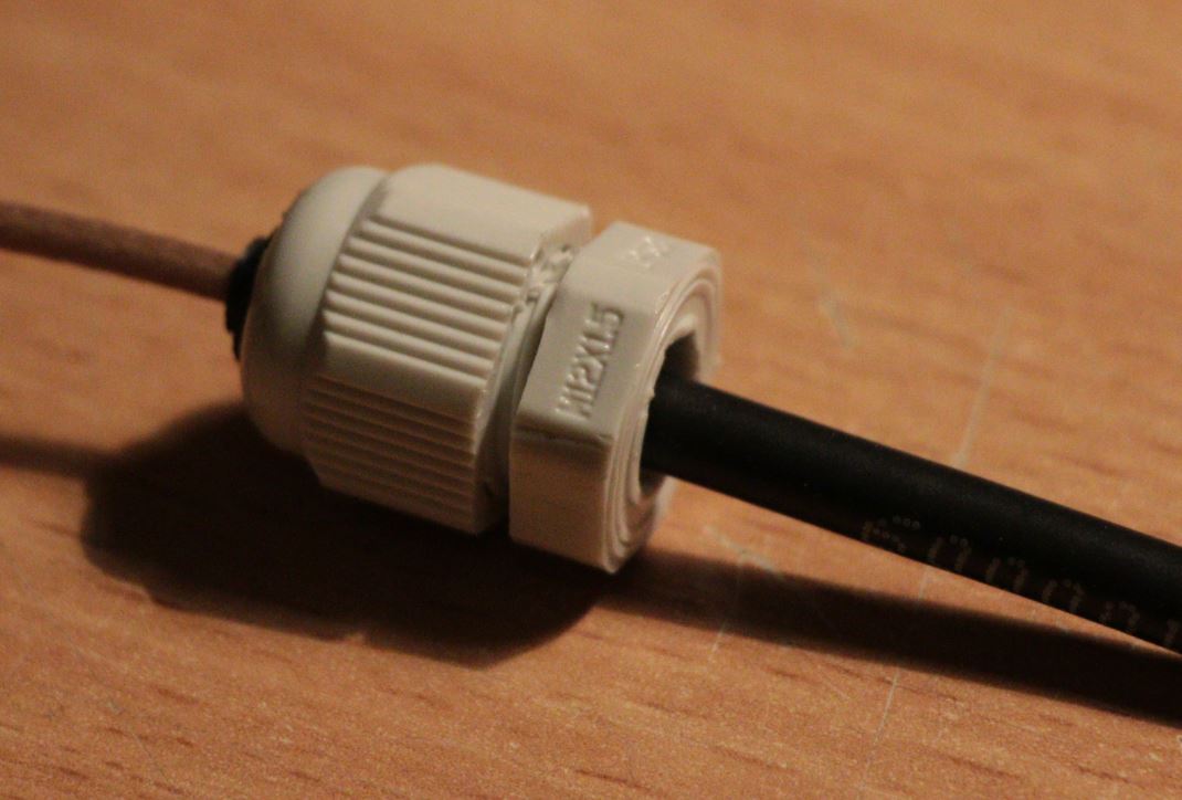
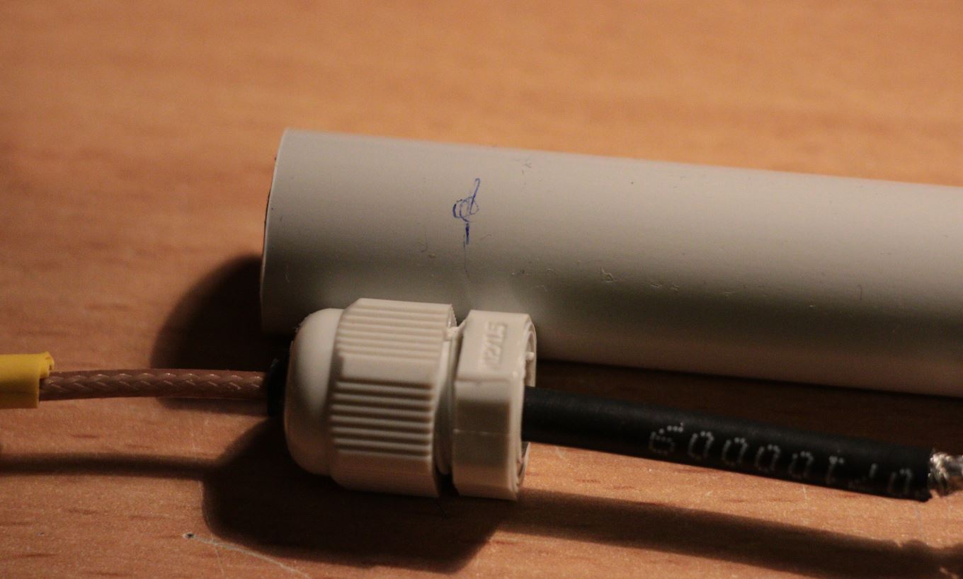
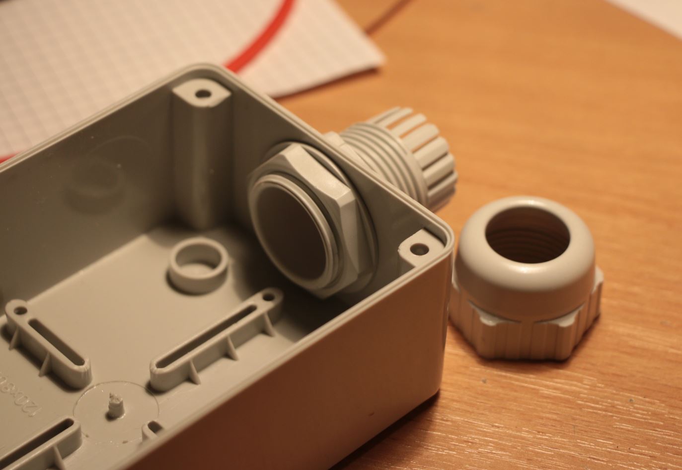
Prepare M12 cable gland like this:

M12 cable gland
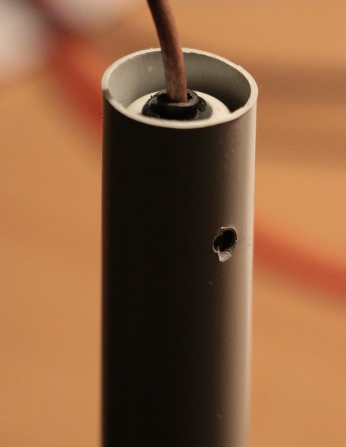
Drill few holes just below the seal (marked with an arrow in photo above).Venting holes will provide draining of the condensation water when antenna is placed outdoor.
Pull the gland over the feed, the seal should be at the connector side:
M12 cable gland with radial venting holes
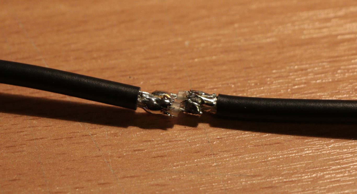
Now solder the RFI skirt (shield), shild of the RG316 and central conductor of the antenna chain together. Solder the central conductor of the RG316 feed to shield of the first section in the antenna chain:
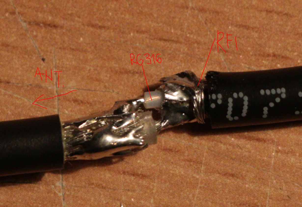
Feed to antenna conection
The antenna is now prepared. Now it’s good time for some preliminary measurements. I measured VSWR with VNA configured as antenna tester:
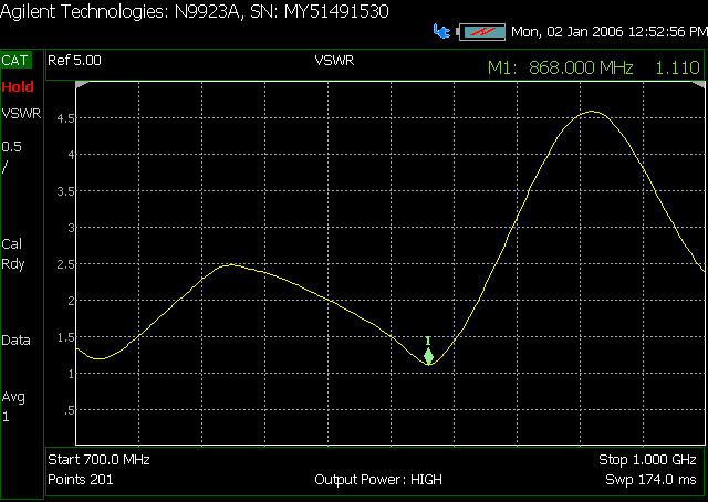
VSWR of the antenna
The drawing of the antenna construction is available in this document.
Antenna housing
The antenna chain is placed within 18mm plastic tube. Cut about 80cm long piece of the UV resistant plastic tube with the diameter 18mm. Drill small hole (4mm) in one end, about 4cm from the edge:
Mark for drilling the venting hole
Slide the antenna chain inside the tube. Align the holes from the gland with the venting hole in the outer tube.
Slide the cable gland inside the tube
Apply hot glue above the gland to fill the gaps between gland and the plastic tube. The PVC tube will probably deform a little. Just cut away the deformed part when cooled down.
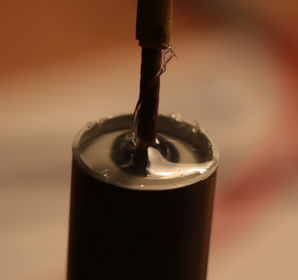
Seal the gap with hot glue
Now it-s time to prepare the housing. I took standard electrical installation housing with dimensions 120x80x50mm:
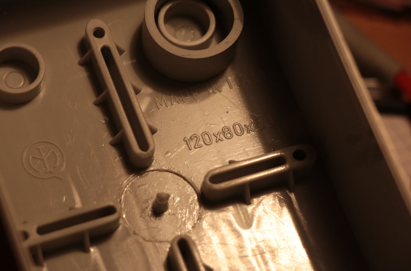
Gateway housing with direct antenna mount
Drill big hole in shorter wall and fit the cable gland. This will hold the antenna in place and provide ingress protection for the gateway electronics:
Big cable gland works as holder and ingress protection
Add rubber cap on the top of the antenna. Cork or other sealant would work as well.
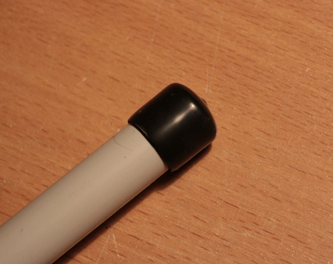
Rubber cap
The final assembly of the antenna ant the gateway housing:
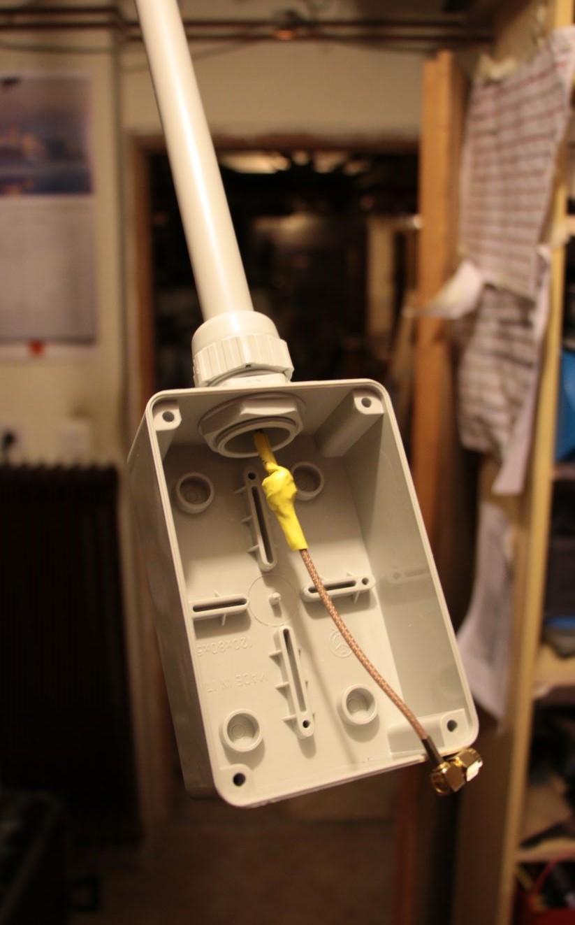
Final assembly
This is the first prototype, where I experimented with the ferrite rings (inside yellow shrink). Measurements showed no significant difference. I think they are not necessary fot this design.
Measurements
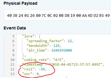
First I made VSWR antenna measurements. The results are shown above. Then I attached antenna to the gateway and checked RSSI+SNR of the nearby end device. I compared this to small helix stub antenna which came with the RAK transciever. The results showed improvement. The antenna seems to work, but it should be tested in the field with some proper distance between the devices.
Before

After
And finally, the LoRaWAN gateway placed on the roof:
Gateway is based on RAK831 donated by Irnas Slovenia (irnas.eu)
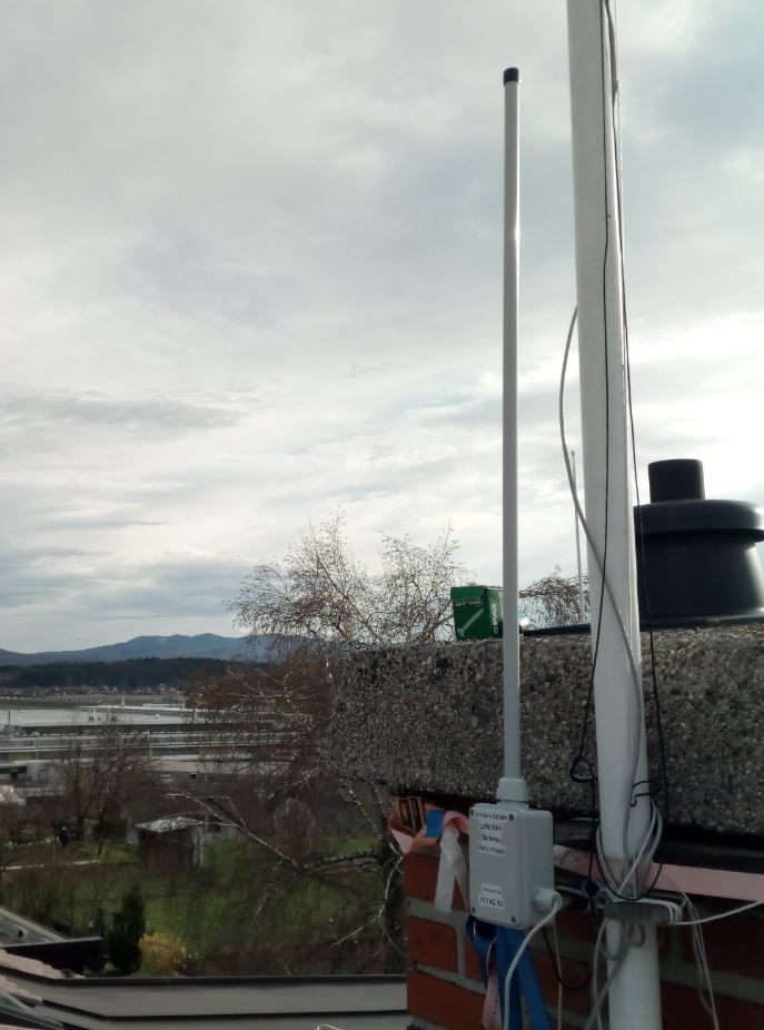
Initial placement

Moved to higher final location