4 element Yagi for 6m
6m band is sometimes called “magic band”. It has combined propagation properties of HF and VHF. When conditions are good, very long DXs are possible. Beside the sporadic E occurence some other requirements are essential. One of the most important pieces of equipment is good antenna. There is no shortcut for good performance in small package. Good antenna is big when lambda is long. For 6 meters, the antenna usually occupies about 3x3m floor area. Here’s my implementation based on Ljubisa Popa – POP YU7EF design EF0604S.
1. Design and simulation
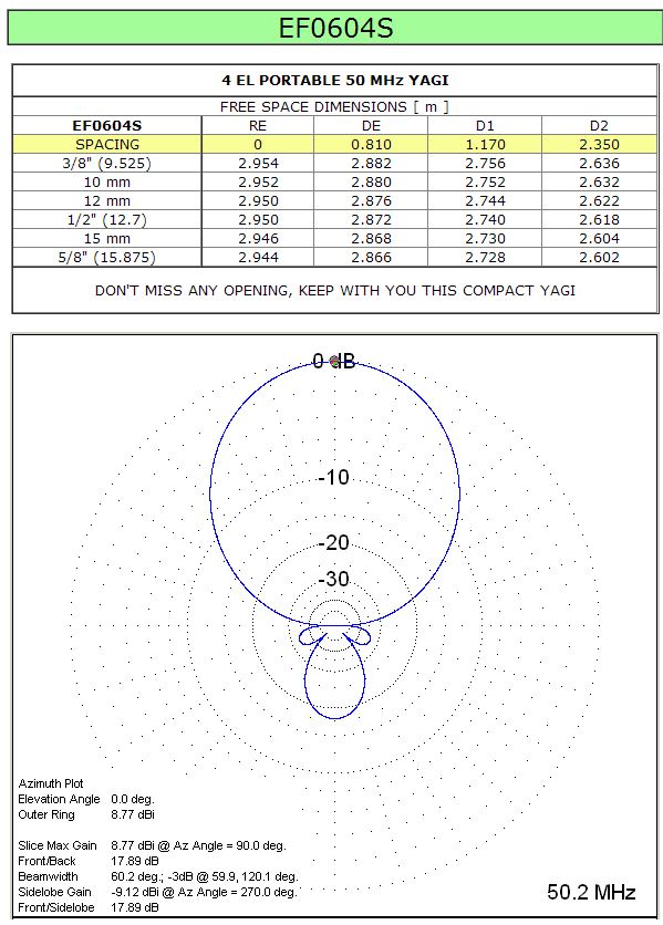
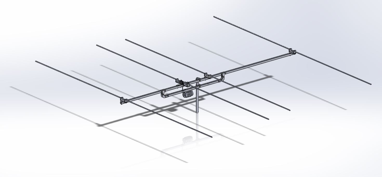
Target frequency bandis 50.0 – 50.5MHz. The elements are 10mm aluminium tubes with simple dismounting and assembly using only basic tools usually present on field. My requirements is to use this antenna not only for stationary work, but also for mobile or even portable (SOTA) operation. The 3D design is shown in following figure:
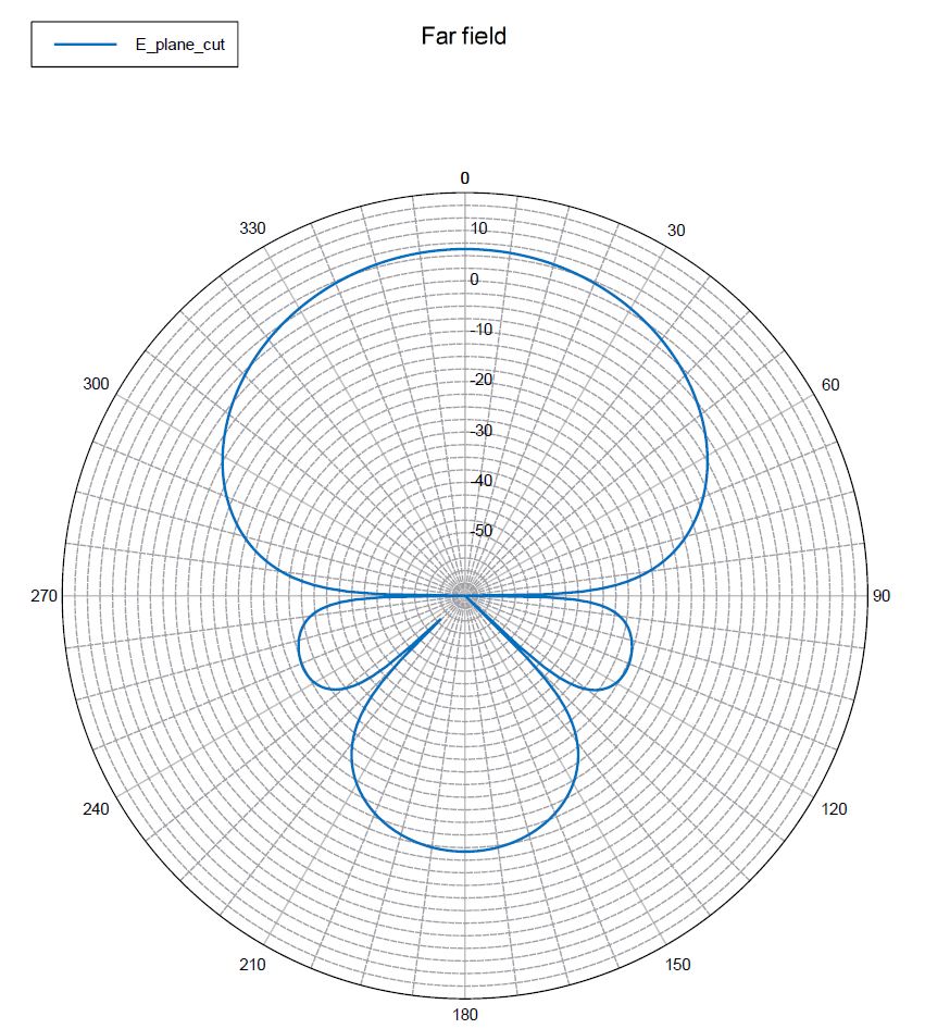
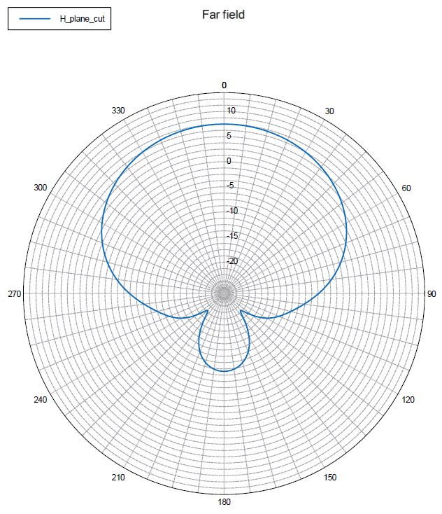
free space dimensions for 10mm tubes are: R: 2.952 mm, Dr: 2.880 mm, D1: 2.752 mm and D2: 2.632 mm. Here are 3D models: STEP, IGES and Parasolid. I run few optimisation cycles with FEKO and realistic geometry. First preliminary results look promising (from left to right: E plane, H plane, radiation and SWR):


2. The construction and material selection
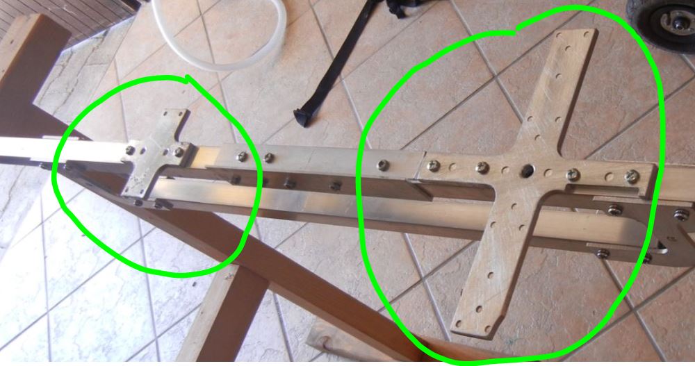
The construction is based on 20 mm square aluminium tubes, 10 mm aluminium tubes and 6 mm aluminium plates. The tubes could be cut few mm longer for fine tuning during antenna testing. Supporting construction is mad from 20 mm square tubes. I cut one long tube into half and join both parts together to have shorter components, just in case I decide to use this antenna during field day by car or during /p operation. The antenna horizontal support is also made from 20mm square tubes. There are four additional aluminium profiles/holders to assemble everything together (PDF Drawing: boomholder). 

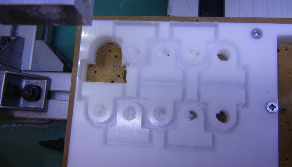
Holders for elements are produced from POM (Polyoxymethylene), which is sold under trade name Delrin and is intended for outdoor use. It is excellent plastics for CNC milling and other machining, like making threads. Ten holders are required for this antenna. Here is PDF drawing for the holder. I made the machining on my CNC mill from a little thicker material, which adds weight, but also strength. The 10 mm Delrin shuld be OK, too. Here are half finished parts:

The mounting holes were drilled and threaded later. Drill the 8mm hole at the base, followed with M4 thread all to the center hole as shown in PDF drawing and following cross section:

Now it’s time to mill some aluminium. There are two types of plates where holders are mounted. One is smaller plate (pdf drawing: plate1) for reflector and two directors (three are required). The driven element has larger plate (pdf drawing: plate-driver) for double holders, because it is divided into two separated pieces. Finished parts should look like these (or better):
3. Elements
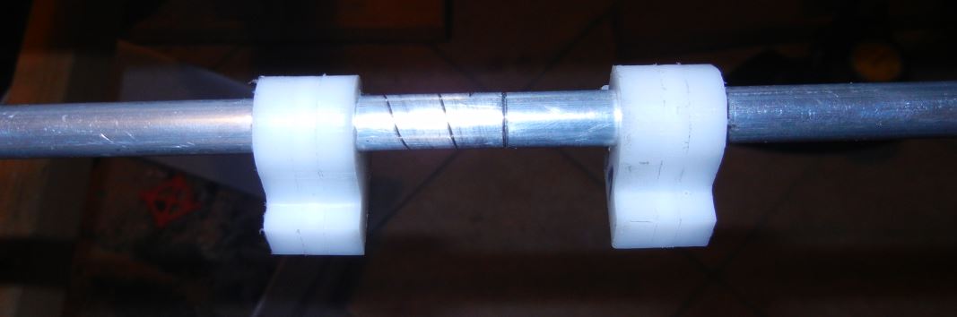
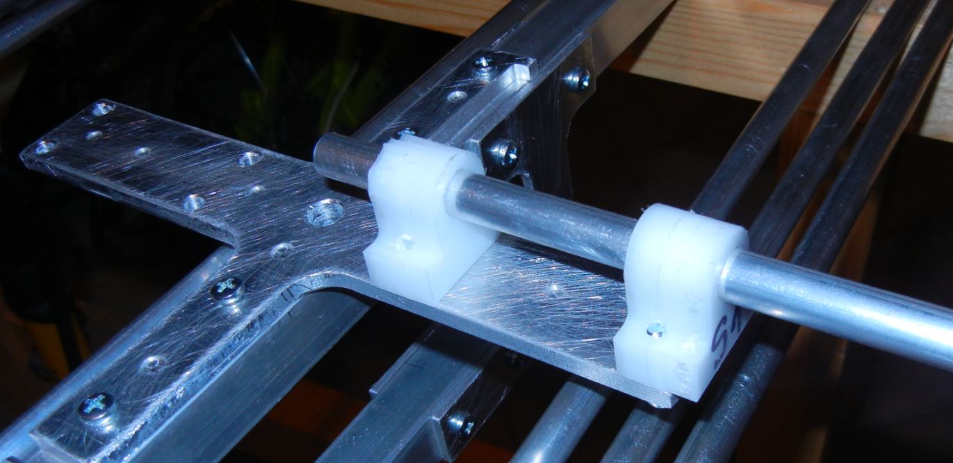
Antenna elements are divided at half. The central section is joined with 100 mm long aluminium rod (PDF Drawing: connectingRod). The connecting aluminium rod has two diameters: 8 mm and 7,8 mm, divided at the center. The aluminium tube for each element is first drilled to 8 mm using lathe. The rod is pressed inside the element tube with 8 mm diameter. The fit should be very tight. I pressed it using lathe tailstock. The rod is pressed only one half inside. The second half of the element should fit loose enough just to provide easy disassembly. Both halves are then equipped with plastic holders, tighten with screws from bottom side and assembled to the plates.


To finish part one of the assembly process I started my 3D printer to produce the cover for dipole connection:
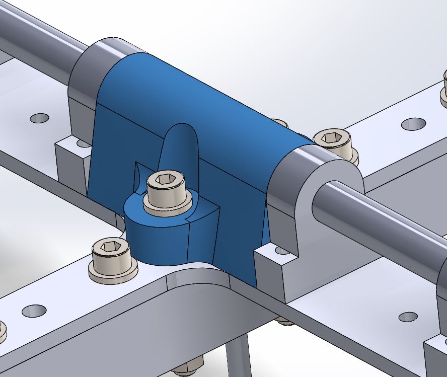
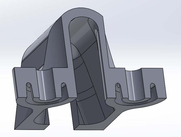
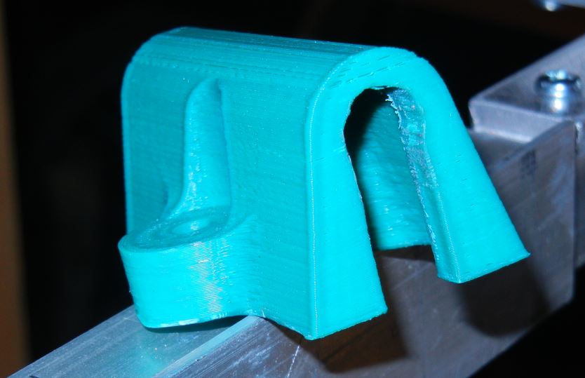

End of part 1 ! Part II: Electrical connection, Testing and tuning
GL Sex! Ne zamuditi najvecje tekmovanje ta konec tedna.