3 axis gimbal for Garmin Virb
I have finished my gimbal project for Garmin Virb Elite action camera and I’ll try to explain how it works and what parts I used.

This is how it looks.

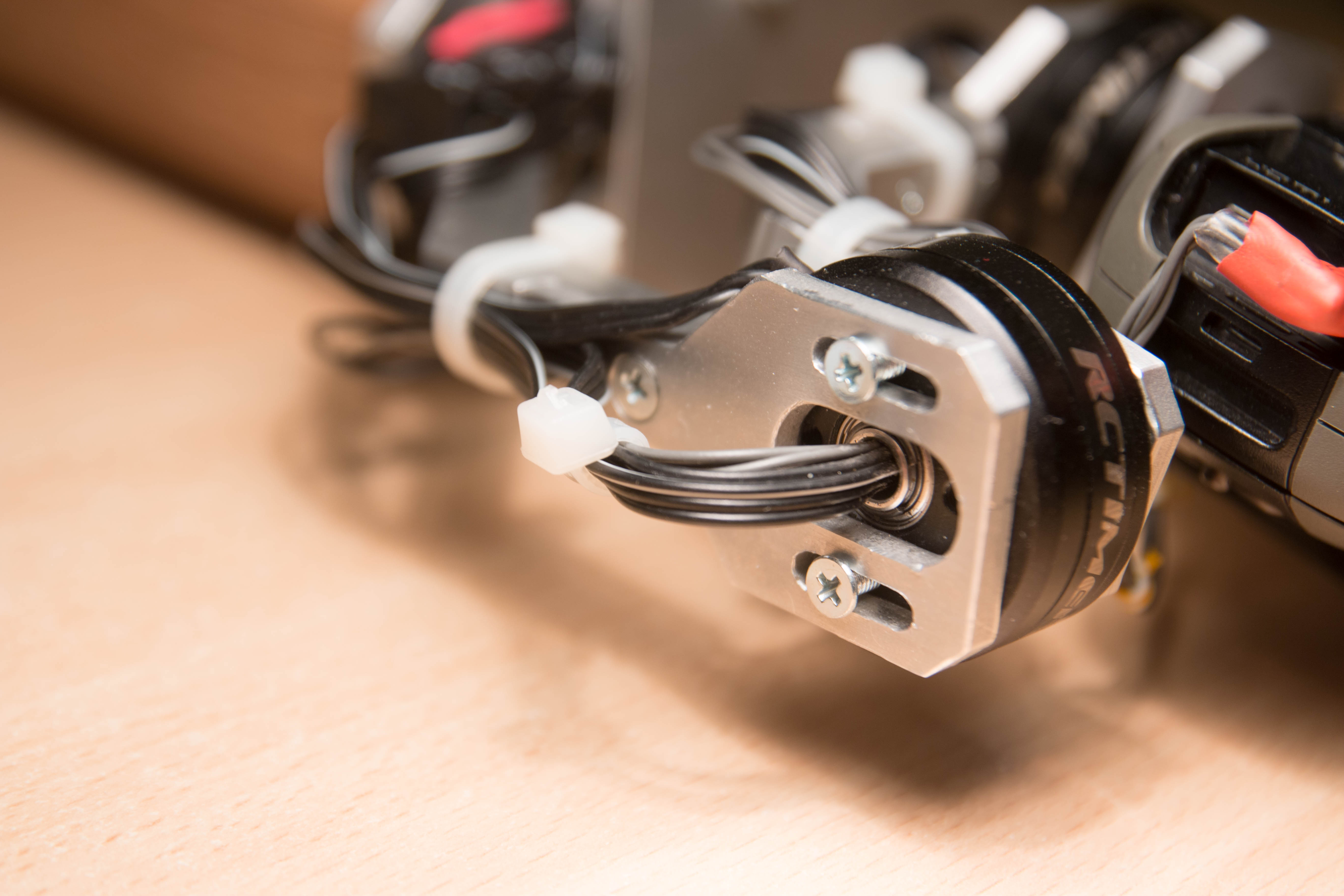
Motors are BLDC with very low KV. All three are alike and have hollow shaft. This enabled me to get wires through the motor shaft and make an improvised slip ring. This solution is capable of few turns in either direction before wires twist too much. All frame parts were machined from aluminum on 3-axis CNC mill. Fortunately I got the design right the first try and I did not have to machine any parts again. I made slots in the design to get little adjustments for gimbal’s center of gravity possible. I was able to get it almost perfect which was more than enough for motors to compensate. Machining took me about a day in the workshop.

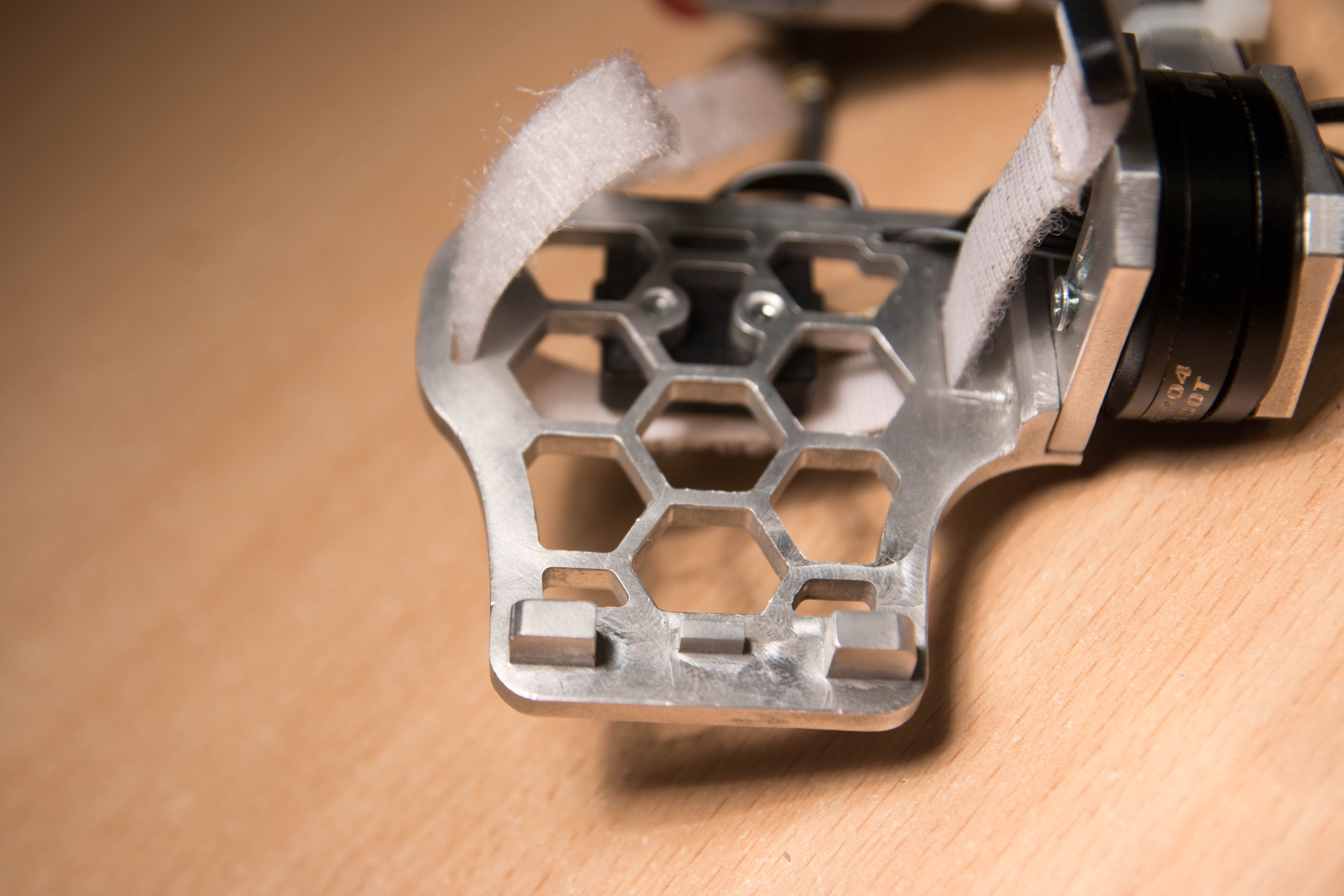
I reverse engineered original mount that came with the camera and designed my own camera plate as I call it to always keep tha camera in the same position on gimbal. Those three teeth at edge of the part were my solution. I also cut out some material to preserve unnecessary weight of the part. Camera is tied to the plate with a small velcro.
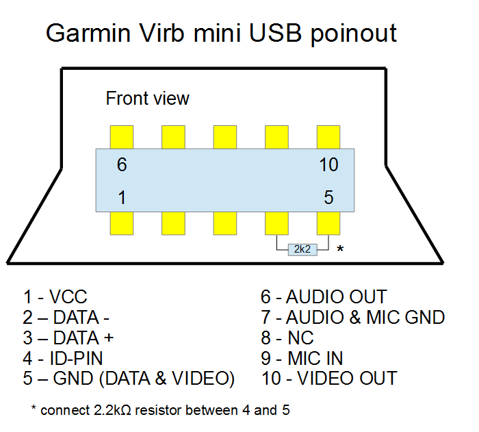
I bought genuine USB cable from Garmin and tore it apart to figure out the pinout. If you like to know more about it, I wrote more here. Camera is outputting live analog video feed through USB. I can also connect external microphone. Port left to the USB on the picture is HDMI. Unfortunately it works in playback mode (no live streaming).

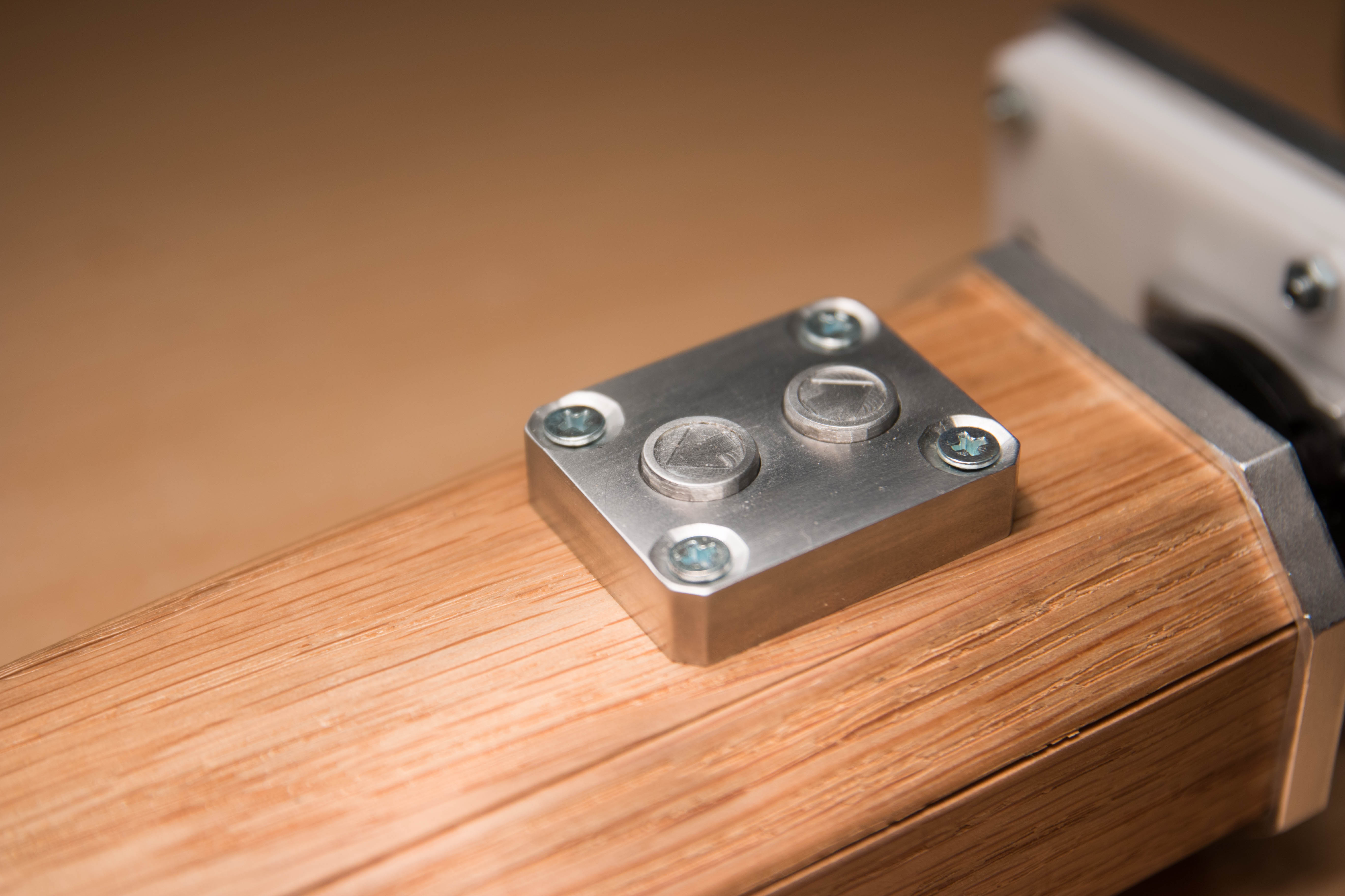
After some time of using my gimbal I added pitch control. IT consist of two 8x8mm SMD buttons in the CNC machined aluminum housing. I also engraved two arrows to make it easier to use for someone who isn’t familiar with such device. To keep the number of wires through motor shaft as low as possible I made a simple resistor divider in parallel with buttons to get all three states of control through only one wire (3.3V=camera tilts up, 3.3V/2=nothing, 0V=camera tilts down).
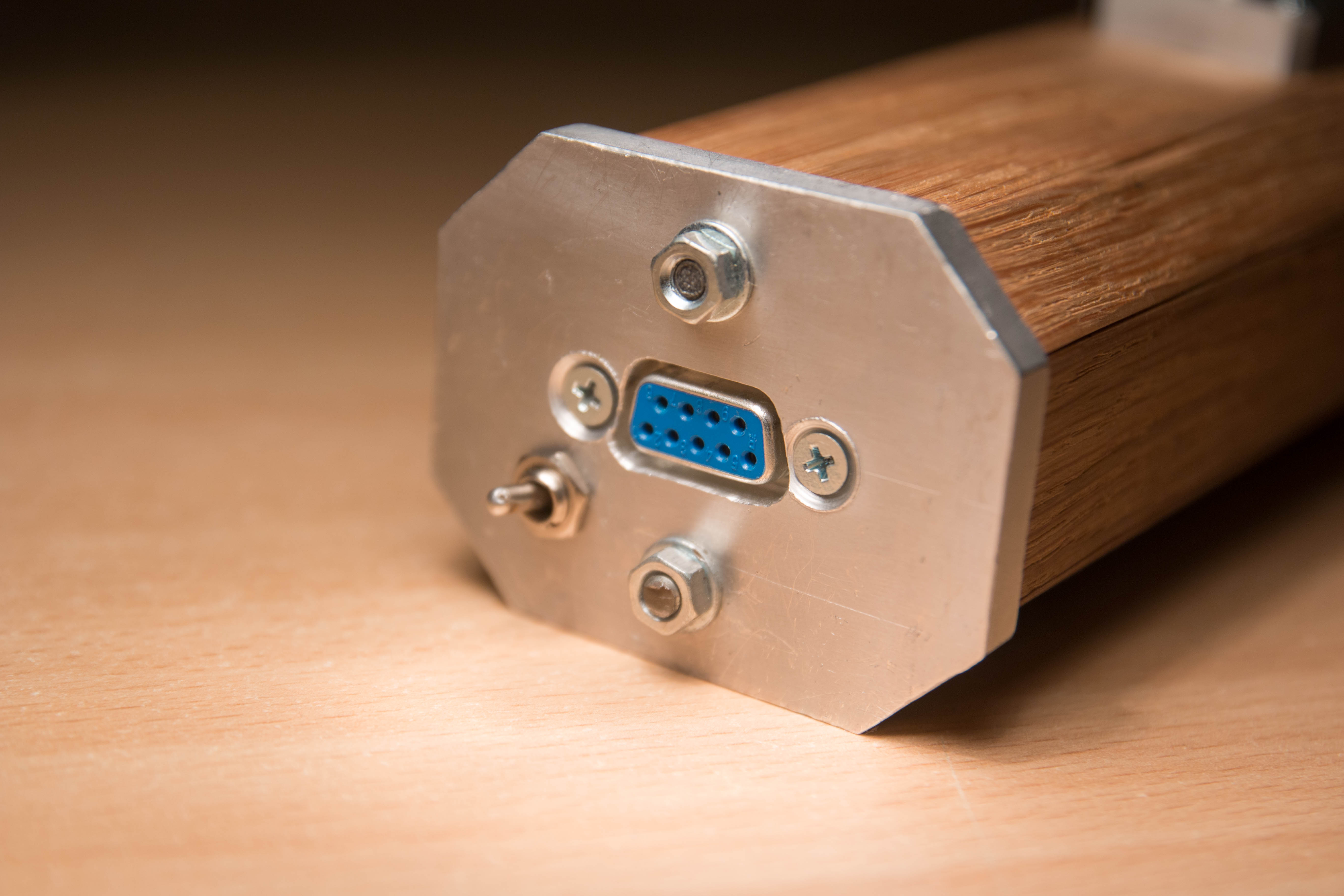
I decided to go with DB9 connector for charging the 3S LiPo battery inside. I only required 4 pins for charging and DB9 has 9. I used the rest 5 pins for 2 RC channels (so I can connect a RC receiver and control the gimbal with it as shown in this video), analog video output (so I can connect external monitor or wireless video transmitter), microphone input and a control button for changing programmable modes of the gimbal operation.
I also made a video transmitter module with a RC receiver. I smiply plug this module in the charging port of my gimbal. It consists of 5.8GHz video transmitter made with boscam module and Frsky 4 channel receiver. You can see its antenna next to the SMA connector of cloverleaf anetnna for video.

I used 3 axis SimpleBGC gimbal controller. It met all expectations and connections was very straightforward. I removed all connectors and soldered wires directly to the PCB to eliminate connector failure possibility and to save some space. Controller uses two sensors (one under the camera and one on the frame) to better determine in what position motors are and greatly increase working angles. Although the controller was expensive I have no regrets buying it because it simply works. Note that I had bad experiance with fakes from ebay before buying genuine one.

SmpleBCG gimbal controller
Here are my current PID settings. It took me some time to get them right. Auto PID helps to get it near perfection but it still needs some human correction. I have follow mode enabled on yaw axis with a deadband of 15°.

First run of the gimbal after getting settings nearly right.
Test outside with gimbal mounted on 3m long pole.
Video demonstrating pitch control.
Pinout of the USB cable on Garmin Virb Elite.
——————————————————————————-
Download CAD files from Grabcad here
——————————————————————————-
Part list:
- Motors: Rctimer GBM2804 Hollow Shaft
- Controller: 32 bit basecam
- Battery: I made a 3S pack from 3 4500mAh LiPo cells
- DB9 connector, 2 pole switch
- 10, 6 and 4 mm aluminum sheet for frame
- 11mm POM plastic for electronics housing
- 4mm oak wood
- few bolts and screws
Video transmitter module
- Boscam TX5823 200mW 5.8GHz analog video transmitter module
- Frsky 4ch receiver
- DB9 connector
- Cloverleaf antenna for 6cm band
Hello
Sort for m’y english but i am french men…
Can you send me for e-mail the schémas about every connection gimbal vire ( db9, power Switch, connector buttons SMD (3.3V=camera tilts up, 3.3V/2=nothing, 0V=camera tilts down) etc…
I lové tour project and y want to make same
Thank you
Emmanuel CARVALHO
Hello!
Here is electrical schematics for pitch control: http://i.imgur.com/6zejRJL.png
For the connection of gimbal controller, motors and sensors take a look at this PDF: http://www.basecamelectronics.com/files/v3/SimpleBGC_32bit_Connection_Diagram.pdf
You can customize pinout for your charging connector (DB9). I have 3S lipo on pins 6-9. Pins 1 and 2 are for RC input of gimbal controller, 3 is analog video output, 4 is microphone in and 5 is control button of gimbal controller. Hope it helps!
———————–
Salut!
Voici les schémas pour le controle pitch: http://i.imgur.com/6zejRJL.png
Pour la connexion aux contrôlleurs, aux moteurs et aux capteurs gimbal, jetez un coup d’oeil à ce pdf: http://www.basecamelectronics.com/files/v3/SimpleBGC_32bit_Connection_Diagram.pdf
Vous pouvez personnalisés les broches pour le connecteur chargeur (D89). J’ai un 3S lipo sur un pin 6-9.
Les pins 1 et 2 sont pour les entrées RC du contrôlleur gimbal, le chiffre 3 est pour la sortie vidéo analogue, 4 est pour l’entrée microphone
et 5 est pour le bouton de control du vérificateur(controlleur, but repetitive, here) gimbal. J’espère que ça aidera. 🙂
Gal
Thank you for your answer,
For connection on the card alexmos everything is OK thank you.
Being a beginner in electronics my buttons ” SMD ” we 4 slots, numbered by 1 have 4, which could be welded. Is you he(it) possible to make me a manual sketch seen top of the connecting between the SMD with the resistances.
Concerning the grip DB9 and more exactly the connecting of this grip has the battery and of the battery has the card alexmos via the power switch can also you make me a small sketch (plan)?
Because if I understood well your system allows to reload your LiPo without defusing(unsettling) her(it), but you do not speak about the grip(taking) JST-XH of balancing of the battery(drum kit).This cable is it connected or not?
Thank you for your help(assistant) and saddened for my ignorance in the domain but I begin.
Manu
PS: Beautiful video in the ski
—————
Merci pour votre réponse ,
Pour les branchements sur la carte alexmos tout est ok merci.
Etant débutant en électronique mes boutons “SMD” on 4 slots, numéroté de 1 a 4,pouvant être soudés. vous est il possible de me faire un croquis manuel vue de dessus du raccordement entre les SMD avec les resistances.
Concernant la prise DB9 et plus exactement le pontage de cette prise a la batterie et de la batterie a la carte alexmos via l’interrupteur d’alimentation pouvez vous également me faire un petit croquis ?
Car si j’ai bien compris votre système permet de recharger votre LiPo sans la démonter, mais vous ne parlez pas de la prise JST-XH d’équilibrage de la batterie. Ce cable est il connecté ou pas ?
Merci pour votre aide et désolé pour mon ignorance dans le domaine mais je débute.
Manu
Here is my SMD schematics for pitch control: http://imgur.com/yTtAu2X
Hi!
Pitch control with your buttons: http://imgur.com/phzqhxW
Connect balance plug to pins 6-9 of DB9 connector and main power leads to alexmos controller (don’t forget to add a switch in series). Main leads of battery are connected internaly to the red and black wire on the balancing connector (such as seen on this picture http://www.milehighrc.com/images/lipos/BalWire.JPG)
I can also make a picture for battery connector if it still isn’t clear.
Gal
Hello
Have you creates a typon for the card PCB of pitch control ? If yes can you transmit it to me please ?
For the plan of the battery this one is it well? http://imgur.com/N0WNhbM
Otherwise I am willing a more detailed plan.
Thank you
Manu
Battery plan is OK as it iss, but in you don’t need to connect 5 and 4, because they are already connected: 4 is on 9 and 5 is on 6.
I did not make any PCB for pitch control. I glued SMD switched directly to the wood with 2 sided adhesive tap (http://www.somi.lt/uploads/images/catalog_src/kahepoosed-teibid_src_2.jpg) and soldered the wires.
Hope it helps, if you have anymore questions, just ask. I’m happy to help.
Gal
So Can i simply connect an external microphone to pins 7 and 9 and still need the resistor between 4 and 5?
Hello!
You have to connect the resistor in order to use an external microphone. Otherwise the camera wouldn’t recognize that a USB cable has been plugged in and show an option on the screen to enable the microphone input.
I visit everyday some blogs and websites to read articles, but this
weblog gives quality based writing.