USB to RS485
Testing of sensors with RS485 using PC without proper interface is not possible. Since RS232 interfaces are very rare, the interface should be hooked to USB. The interface between USB and RS485 can be soldered with one of the many FTDI interfaces with added RS485 driver, or bought as assembled module. There is always the third option. I made it from scratch.
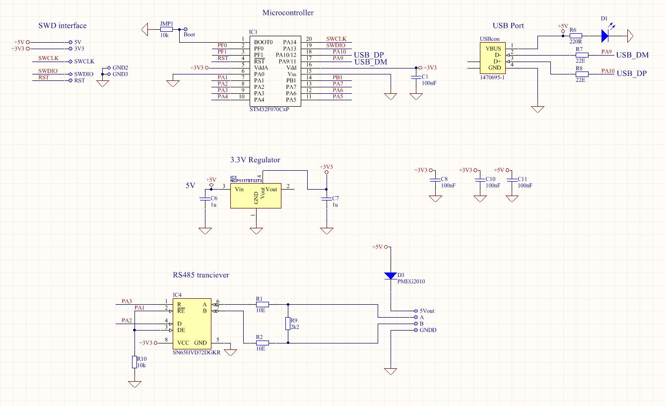
I took smallest STM32F0 with USB and UART interface. The best thing with UART in the STM32F0 is that signal for driver enable is provided within hardware. The complete pinout of the microcontroller is:

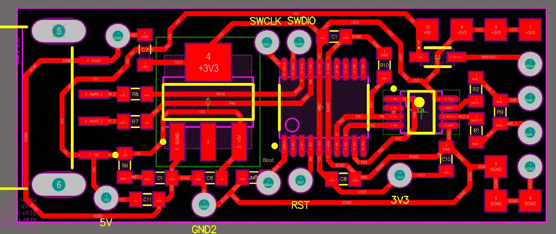
The hardware part is easy. The complete PCB is one-sided. I kept it as minimalistic as possible. There are three active components: voltage regulator, microcontroller and RS485 transceiver. The complete schematic:
The PCB is single sided:

Altium files can be requested via email.
The documentation in PDF file: USB2RS485-doc
For all who want to produce the PCB with the toner transfer technology is here the PCB, mirrored and with 1:1 scale: USB2RS232-tonertransfer
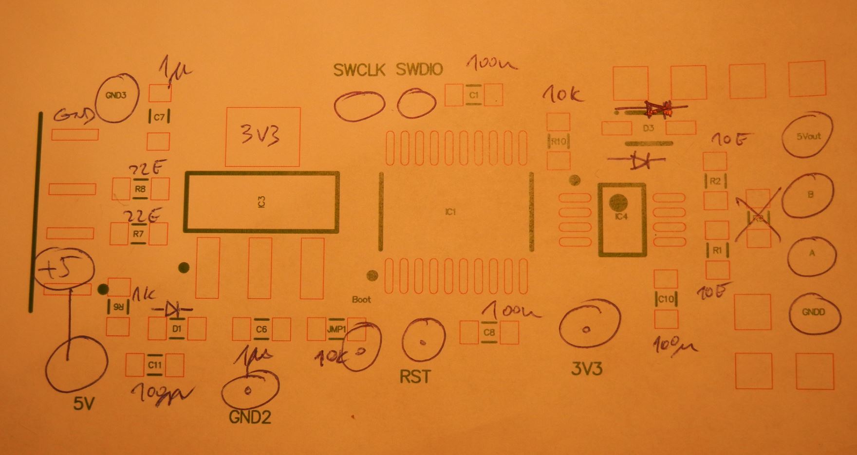
And the most useful sheet of documentation for assembling:
After soldering it’s time to put the module to life:

The project, generated from the MX cube is almost all we need. There are few things to add:
- retransmit bytes received from USB to UART
- forward bytes received via UART to USB
- add serial line coding interpretation and reflect it in the hardware UART
The code for sending bytes from UART to USB is within main endless loop:
if (HAL_UART_Receive_IT(&huart2, &aRxBuffer, 1) == HAL_OK) CDC_Transmit_FS(&aRxBuffer,1) |
Code to send data from USB to UART is within CDC_Receive_FS() function:
static int8_t CDC_Receive_FS (uint8_t* Buf, uint32_t *Len) { /* USER CODE BEGIN 6 */ USBD_CDC_SetRxBuffer(hUsbDevice_0, &Buf[0]); USBD_CDC_ReceivePacket(hUsbDevice_0); HAL_UART_Transmit(&huart2, Buf, *Len, 100); return (USBD_OK); /* USER CODE END 6 */ } |
And finally, the code to set the UART line parameters are within USB CDC_Control_FS() function:
/*******************************************************************************/ /* Line Coding Structure */ /*-----------------------------------------------------------------------------*/ /* Offset | Field | Size | Value | Description */ /* 0 | dwDTERate | 4 | Number |Data terminal rate, in bits per second*/ /* 4 | bCharFormat | 1 | Number | Stop bits */ /* 0 - 1 Stop bit */ /* 1 - 1.5 Stop bits */ /* 2 - 2 Stop bits */ /* 5 | bParityType | 1 | Number | Parity */ /* 0 - None */ /* 1 - Odd */ /* 2 - Even */ /* 3 - Mark */ /* 4 - Space */ /* 6 | bDataBits | 1 | Number Data bits (5, 6, 7, 8 or 16). */ /*******************************************************************************/ case CDC_SET_LINE_CODING: linecoding.bitrate = (uint32_t)(pbuf[0] | (pbuf[1] << 8) | (pbuf[2] << 16) | (pbuf[3] << 24)); linecoding.format = pbuf[4]; linecoding.paritytype = pbuf[5]; linecoding.datatype = pbuf[6]; huart2.Init.BaudRate = linecoding.bitrate; switch (linecoding.format) { case 0 : huart2.Init.StopBits = UART_STOPBITS_1; break; case 1 : huart2.Init.StopBits = UART_STOPBITS_1_5; break; case 2 : huart2.Init.StopBits = UART_STOPBITS_2; break; } switch (linecoding.paritytype) { case 0 : huart2.Init.Parity = UART_PARITY_NONE; break; case 1 : huart2.Init.Parity = UART_PARITY_ODD; break; case 2 : huart2.Init.Parity = UART_PARITY_EVEN; break; } //UART_WORDLENGTH_7B switch (linecoding.datatype) { case 7 : huart2.Init.WordLength = UART_WORDLENGTH_7B; break; case 8 : huart2.Init.WordLength = UART_WORDLENGTH_8B; break; } HAL_RS485Ex_Init(&huart2, UART_DE_POLARITY_HIGH, 0, 0); break; |
The complete project is hosted on GitHub>>> https://github.com/s54mtb/USB2RS485
The driver for the USB/CDC device class can be downloaded from: http://www.st.com/content/st_com/en/products/development-tools/software-development-tools/stm32-software-development-tools/stm32-utilities/stsw-stm32102.html or local copy: VCP_V1.4.0_Setup
I will use this small module for testing sensors, which I have under development for my vineyard weather station: humidity, air pressure, temperature, wind, illumination, soil parameters, etc…
Please send comments or questions via form below this post.
I think you need an external clock for the STM32F070 series of chips – it doesn’t have built in usb clock recovery, unlike the STM32F042 or STM32F072 series (stm32F0X2). You may be able to get around it by continuously adjusting the clock according to the USB SOF in software (I think I’ve seen someone do this before).
See this page, the rightmost column of the table, STM32F0X0 is not marked as “crystal-less”, while STM32F0X2 and STM32F0X8 are marked as crystalless.
> http://www.st.com/content/st_com/en/products/microcontrollers/stm32-32-bit-arm-cortex-mcus/stm32f0-series.html?querycriteria=productId=SS1574
I suspect it works anyway, but maybe temperature variations or using a different computer may cause the usb to not work properly if the clocks are too far out of sync.
You are right. It works at room temperature conditions. I tested it on about 10 modules. Anyway thank you for pointing this out. I will test with wider temperature range.
I just found out one nasty bug with the USB CDC buffer size. When sending more than 4 bytes at once, the microcontroller issued hard fault. I changed APP_RX_DATA_SIZE and APP_TX_DATA_SIZE to 256 (in file .\Src\usbd_cdc_if.c). Now it works much better. It is possible to extend this even more, but the device will then soon run out of available RAM.
Thank you so much. I just got the same trouble with USB stack and now I fixed it by adjusting buffer length!
Documentation for double sided PCB:
http://e.pavlin.si/2016/08/17/usbrs485-converter-on-a-double-sided-pcb/