Cheap sh*t magnetic pickup
Do you ever wondered how much magnetic field garbage is around you? This is cheap and easy build to measure magnetic noise or to compare which switching supply is more sh*tty.
Near field probes are nothing new. It’s easy to find one via web search. Here is one good reference for H and E field probes which I found via google image search:

EMC near field probes for H and E field
What I am describing here is shown on the left above in the first row.
I took regular RG58, about 30cm (1 foot) long. I removed outer isolation and shield exactly at the middle using sharp knife. I was trying not to cut too deep keeping inner dielectric in one piece. Here is sketch for reference:

Aproximate dimensions of RG85 coax with the gap
After few minutes I got clean gap in outer coaxial shield:

Shield gap
After this preparation it was time to source some broken power supply (switcher). I as looking for common mode choke, which is usually in the primary side of many DC/DC or AC/DC power supplies. What I wanted is smaller choke, so I looked in smaller power supplies. It is also possible to wind such common mode choke by winding some 20-50 windings of bifilar wire around ferrite ring. Such rings are also part of any switcher.
Next thing was housing. I took regular 1,6mm double sided FR4 and cut few pieces for simple soldered shielded box. I drilled two holes for magnetic pickup side and one hole for output cable. All tiny bits and pieces described above are shown in this photo:

Sides of a shilded box with holes for coax and Common Mode Choke soldered to perforated universal board
Coax with gap was folded into the loop and shields at both ends were soldered to the FR4 through two holes. Diameter for holes for FR4 is 5mm:
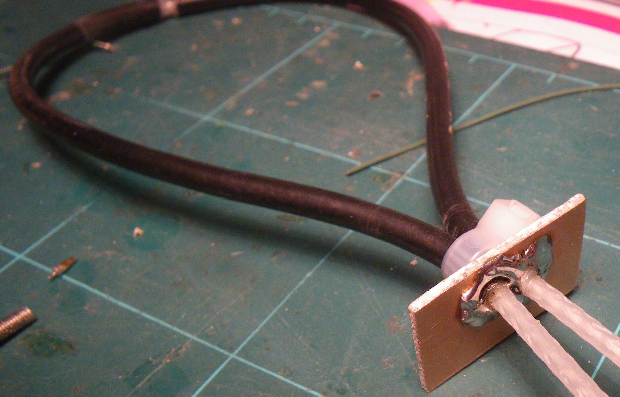
The pickup loop

One zip-tie was used to fix the loop.
Same connection was repeated at the other side with single hole. I soldered about 2m of RG58 with BNC connector. This side will be connected to oscillocope or spectrum analyser.
To solder the coax to the hole I first put the coax through the hole, and pushed the shield against the copper wall to expand like skirt of a dancer. Then I cut excess shield away and solder this to the copper wall:
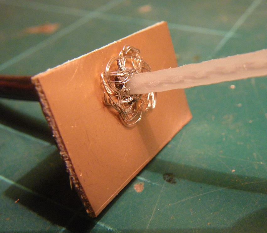
Prepare shiled skirt

Solder to the copper wall
Then I soldered both walls with coax cables to the base and connected coax cables to the choke.

It’s not nice soldered but who cares. It’s just prototype for proofing the concept
At the end I soldered FR4 walls all around to close the box.

Closing the shield – no screws, just solder
And finally it was time to test the probe. I connected the magnetic probe to the oscilloscope. The loop was placed in front of the DMM display:

Pickup in front of the 34401A DMM
And the oscilloscope measured signal sequence for driving the 7-segment display:

Signal sequence driving 7 segment display
Then I put the probe around the AC/DC switching supply:

Loop around AC/DC supply
And the result:

Signal from AC/DC supply
And finally, I put small M6 screw in the lathe and turned few hundred turns of enamel wire. This coil was then connected to the power supply with the current limit 0,5A.

Generator coil
I generated random pulses and measured signal picked by loop. I put the loop into the direction of the source coil. Both were on axis and the measured signal was:
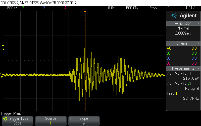
Measured signal when source and pickup as on axis
The RMS of the measured signal was above 200mV.
Then I turned pickup loop perpendicular to the source coil to check if there is any difference. The signal should drop and it really did:

Signal when coils were perpendicular
The RMS droped about four times. It looks the probe is working and I could measure some signals from other known and unknown sources.
For any questions or comments please use form at the end of this page.
Thank you for reading!