6×1 antenna switch
This is complete project for 1×6 antenna switch. It was bult in more than 50 pieces around the world and performs really good. Even big guns use it for their systems. The project was designed with help from other OMs (S55O, S59MA, S50LD, S51CT, S51ZJ, SM2WMV/SJ2W and others).

6×1 antenna switch
The schematic is “boring”: nothing special. Just connectors and relays and some protection:

Schematic for 1×6 antenna switch
PCB board is double sided, “sunshine” design. This simetrical design provides equal characteristics for all 6 outputs:

Connector side of the PCB

Relay side of the PCB
Altium files can be requested via email.
If you don’t have altium designer, just send this file (with GERBERs) to your favourite PCB maker (I prefer PCBWay) and order 1,6mm PCBs:

Gerber and drill files for the project
Good antenna switch has no value without proper housing. I designed folded sheet metal housing. Here are complete documentation for 2 parts including 3D step files:

Housing – PDF documentation
Here is assembly process in pictures:
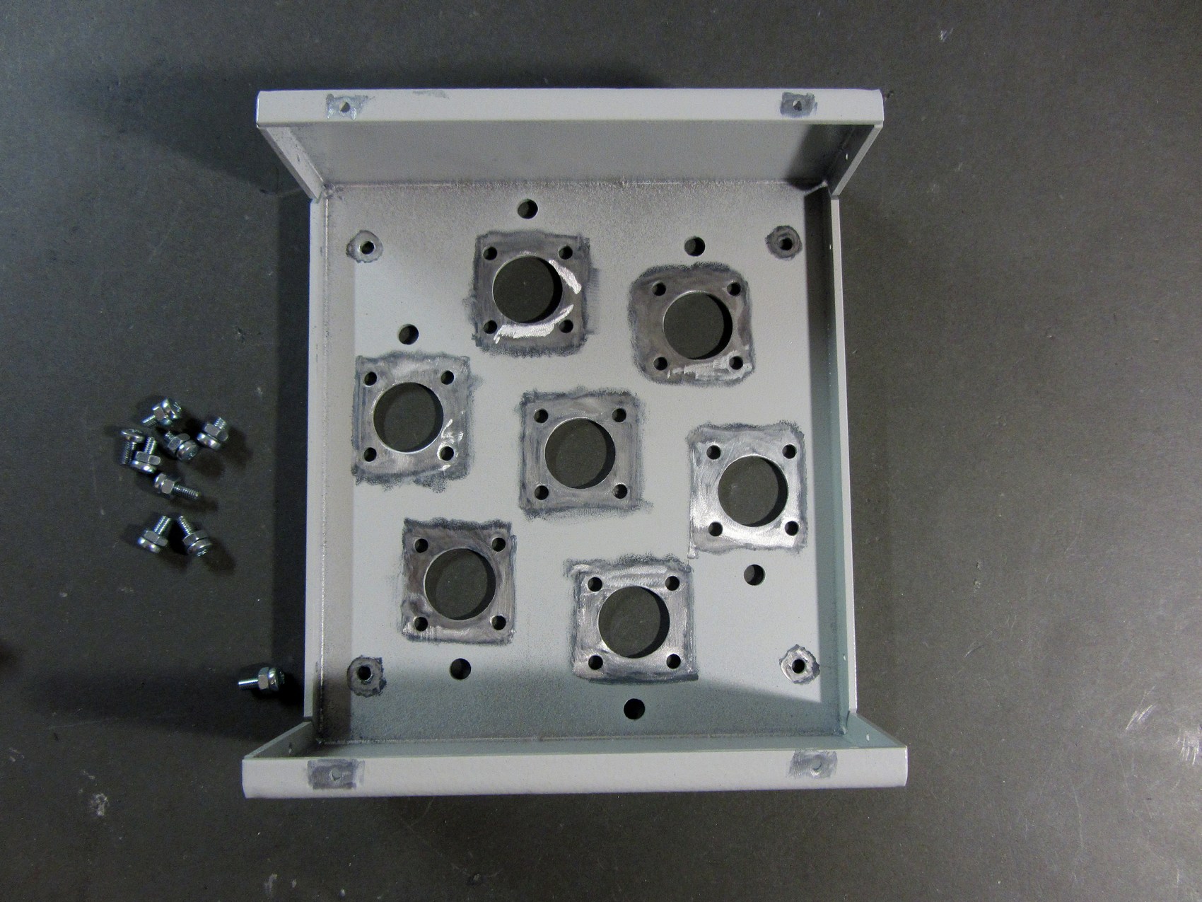

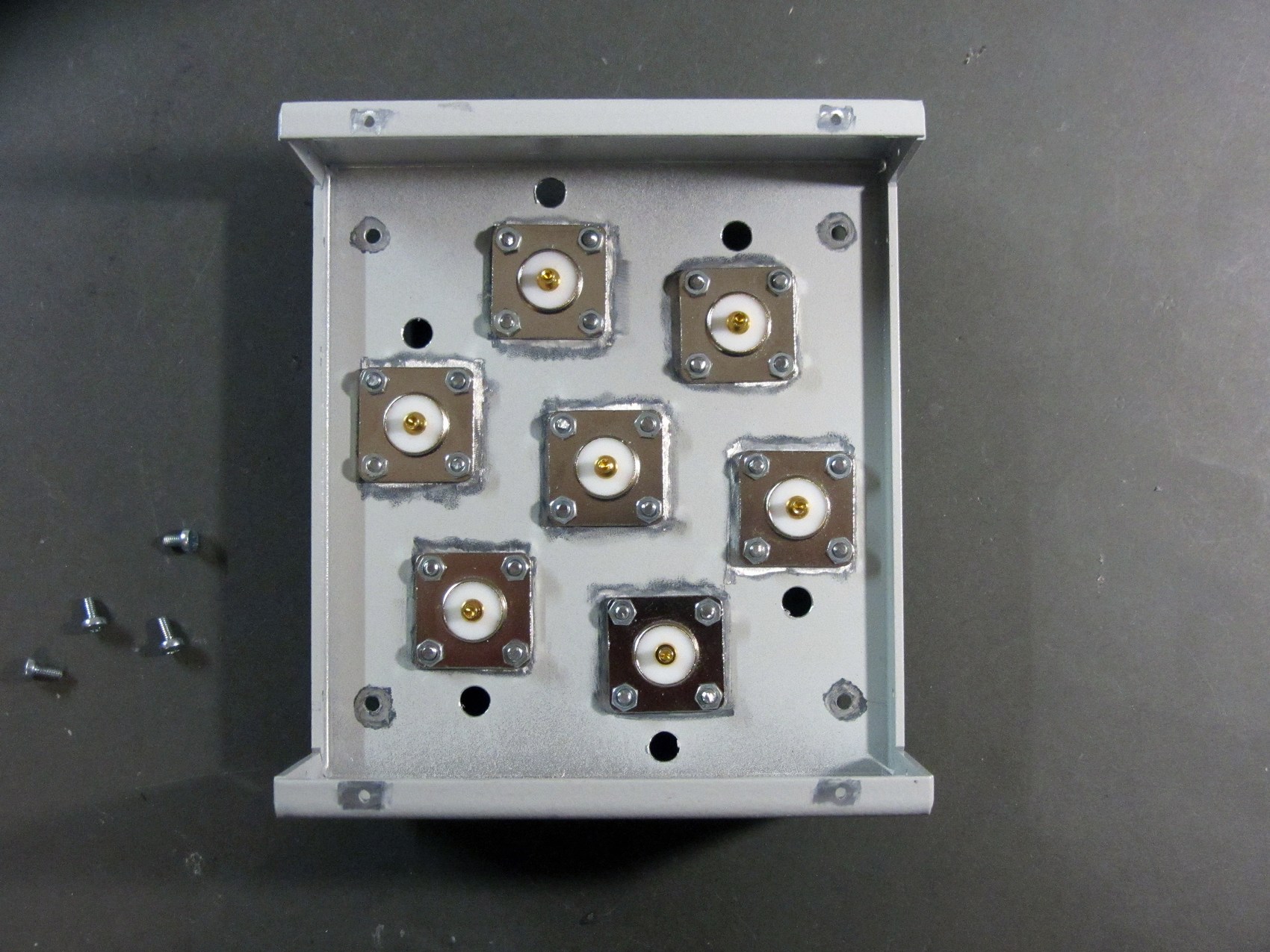


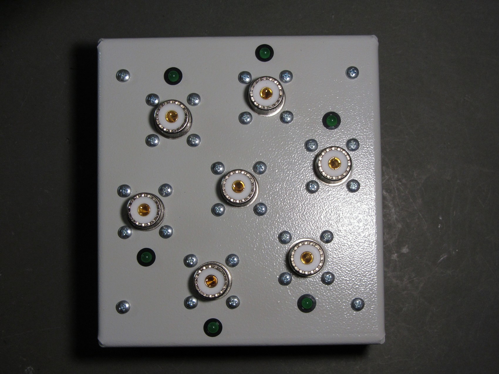
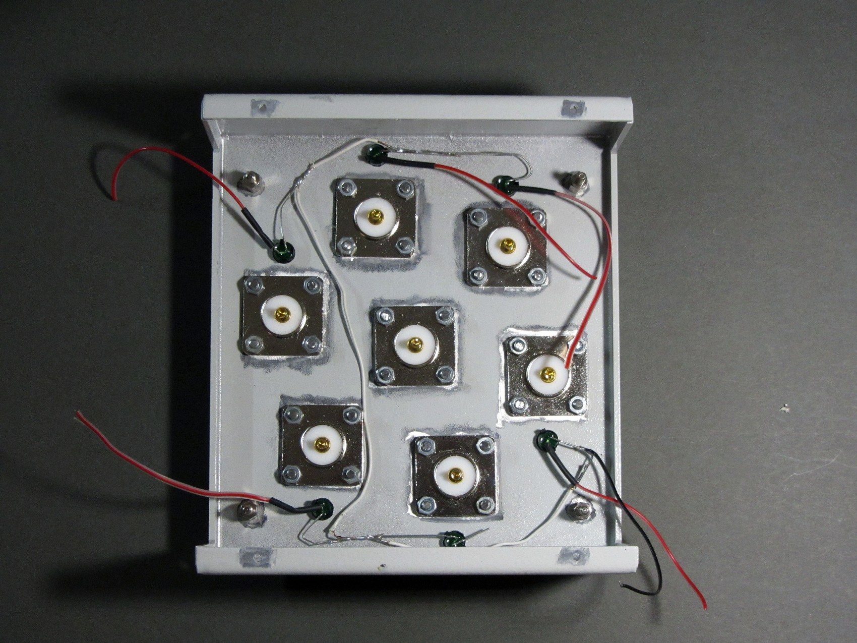


Here is another gallery with step-by-step assembly process on S55O page.
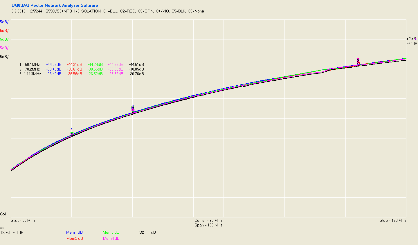
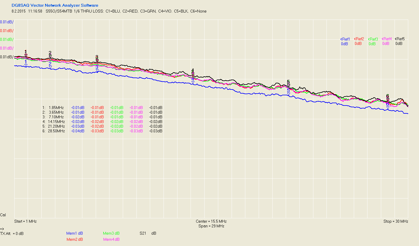
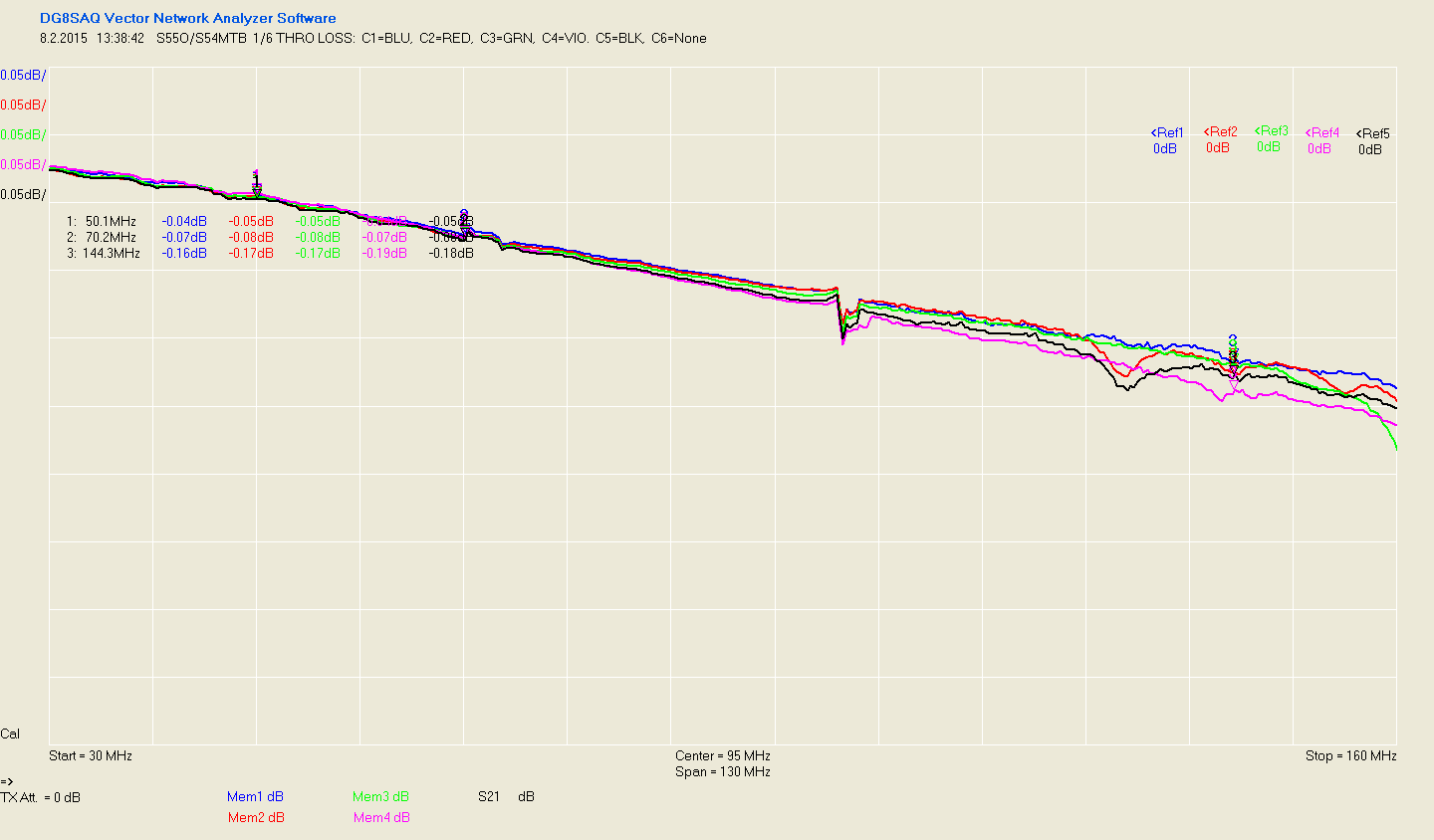
And final test (isolation and through loss) for all HF bands including 6m:
-

- Final testing results


The Relays are:
Fujitsu FTR-K1CK012W
https://octopart.com/ftr-k1ck012w-fujitsu-795639?r=sp
Nice project! Will the PCB be for sale?
73 OZ1QZ / John
Easiest and most cost effective is to order PCB at some low cost Asian vendor. Gerbers are available from the link above.
Marko
Great project,I will collect and share it