Particle Sensor with LoRa
Two PCBs from earlier projects were used in this project:
- LoRa breakout board
- Sensor PCB with Si7013 humidity sensor from multisensor LoRa project
- … and particle sensor.
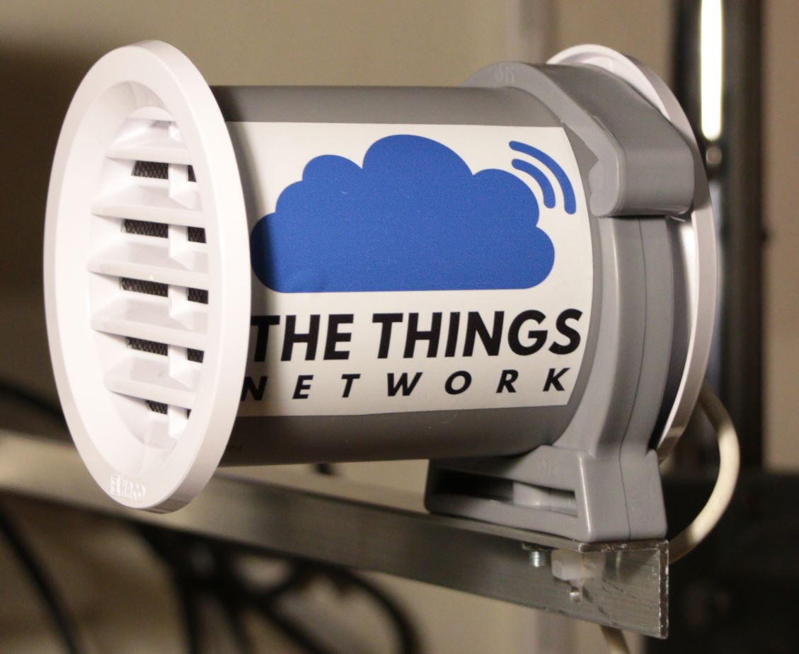
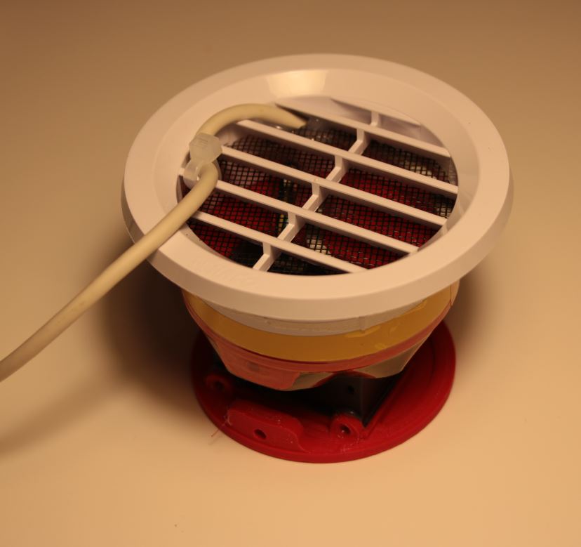
Finished particle sensor in housing, ready for the TTN
Particle sensors could be cheap and easy to use. Disadvantage of lowest cost PM sensors is lack of “calibration”. The best method to measure particle content dispensed in the air is to collect the air sample and analyse it off-line in the laboratory with proper equipment (not cheap at all). Optical particle counting sensors use the light scattering method to detect and count particles in the operating concentration range in a given environment. A laser light source illuminates a particle as it is pulled through the detection chamber. As particles pass through the laser beam, the light source becomes obscured and is recorded on the photo or light detector. The light is then analyzed and converted to an electrical signal providing particulate size and quantity to predict concentrations in real time. The described particle sensor provides information on the particle concentration for given particle concentration range with statistical methods compared to distribution of some common pollutants, like cigarette smoke. The result depends on position of the particle flying by the light beam, its speed and shape.
I used the Honeywell HPM sensor, which is somehow “calibrated” to the tobacco smoke concentration. The result is not accurate, but is good enough to detect the trends and sudden concentration changes. The HPM sensor is not expensive and gives usable results as far as we know how to interpret the output values.
Required materials
Almost all materials are shown in the following photo:

Required essential materials for this sensor
BOM:
- LoRa breakout board
- Sensor board from multisensor project with cut away all sensors except Si7013
- One 8-wire cable with connector Molex 51021-0800 or equivalent (I found cheap chinese cables on ebay – they are available from 2 to 10 wires, with 1,25mm pitch connector)
- One 4-wire cable with same 1,25mm pitch (search ebay for “1.25mm Pitch Electronic Cable Single Header Connector Wire 20cm 2P-10P“)
- Two ventilation grills, diameter 70mm (see photo above, check your local hardware store)
- Piece of 70mm sewer plastic tube, cut to 110mm long piece
- Plastic holder for the 70mm tube
- Two 3D printed parts (equal) for holding the HPM sensor in place
- Small helical antenna

3D printed part (holder for HPM sensor)
The sensor needs only 5V power supply (most common 5V wall adapter used for phone/tablet charging). I didn’t put this on the BOM list because everyone has different supply of the 5V supplies 🙂
Connection diagram
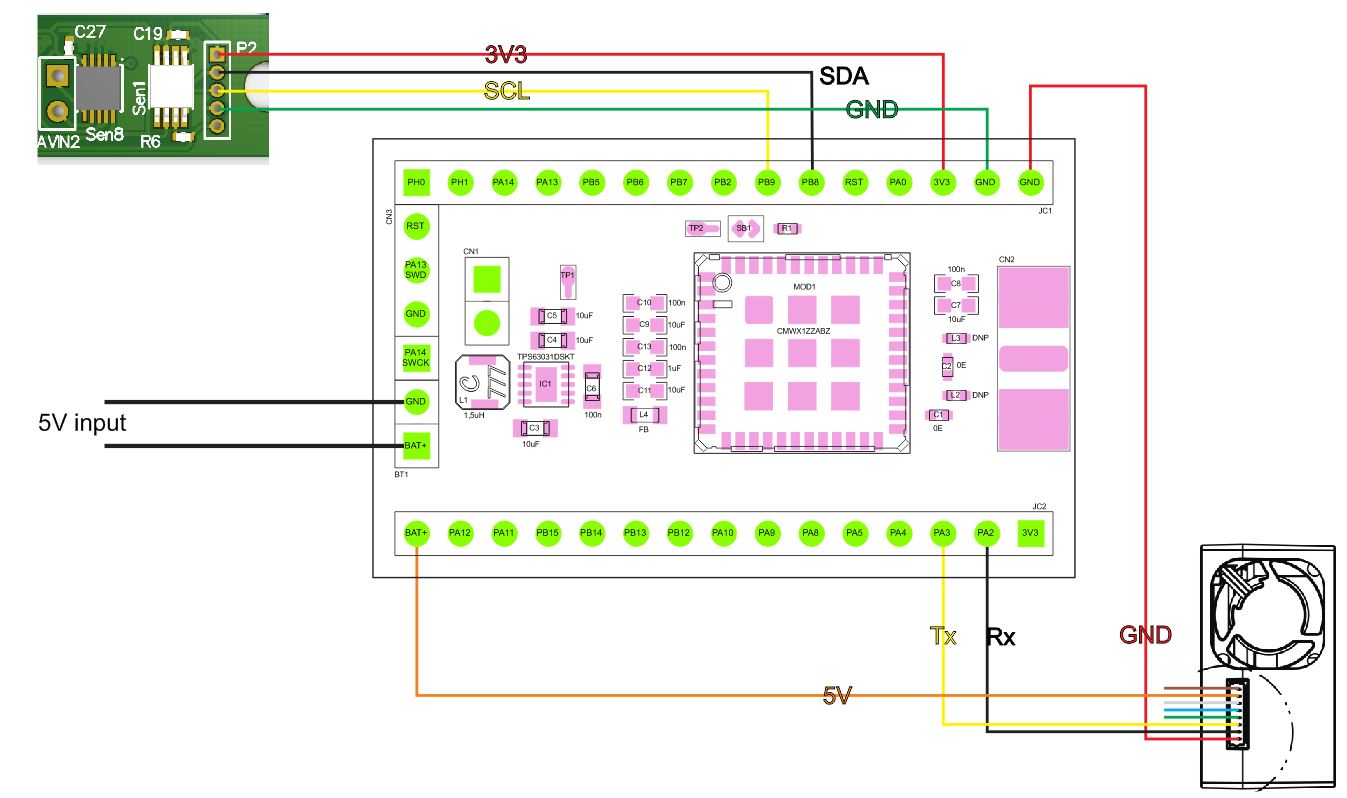
Wiring diagram
There is nothing special about wiring the whole sensor. Just connect the Si7013 to I2C pins and HPM sensor to USART2 pins. The Si7013 is powered bz 3,3V and HPM sensor is powered from 5V. All required interconnections are shown above with the colors of the cables from ebay.
Assembly
I used hot glue to assemble everything together. There should be two or three holes drilled in one holder: one for Si7013 sensor and other one or two for cable from HPM sensor and power supply cable.
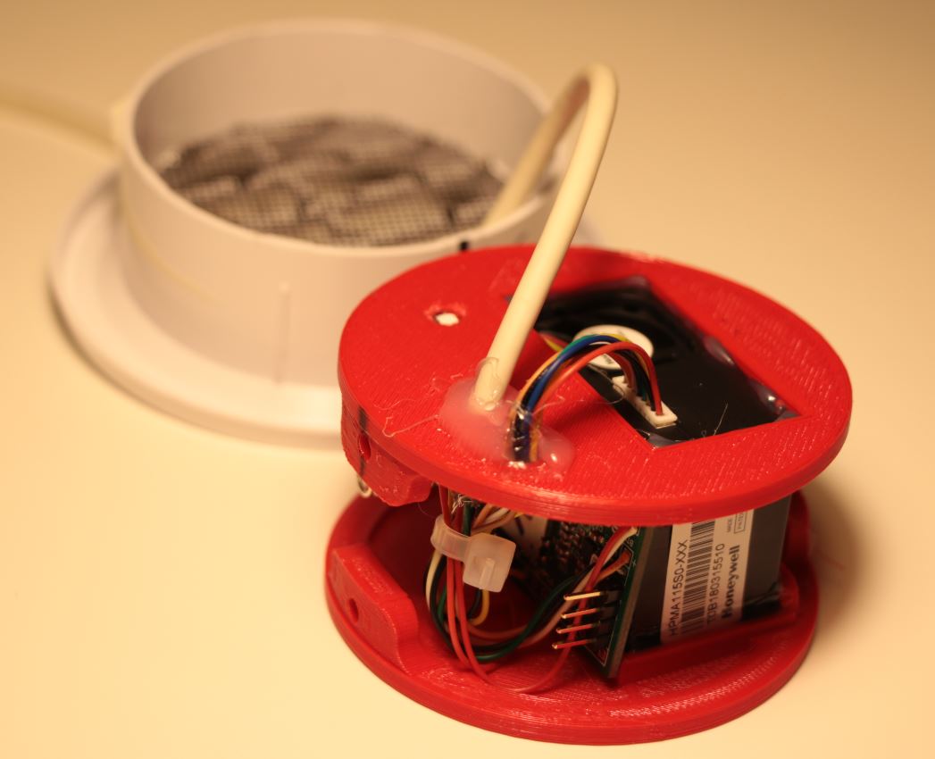
Cables and holes
Then solder the LoRa breakout board and Si7013 board. Attach the Si7013 board from the inside:

Attach Si7013 from the inside with help of hot glue
Dont’t forget the antenna:
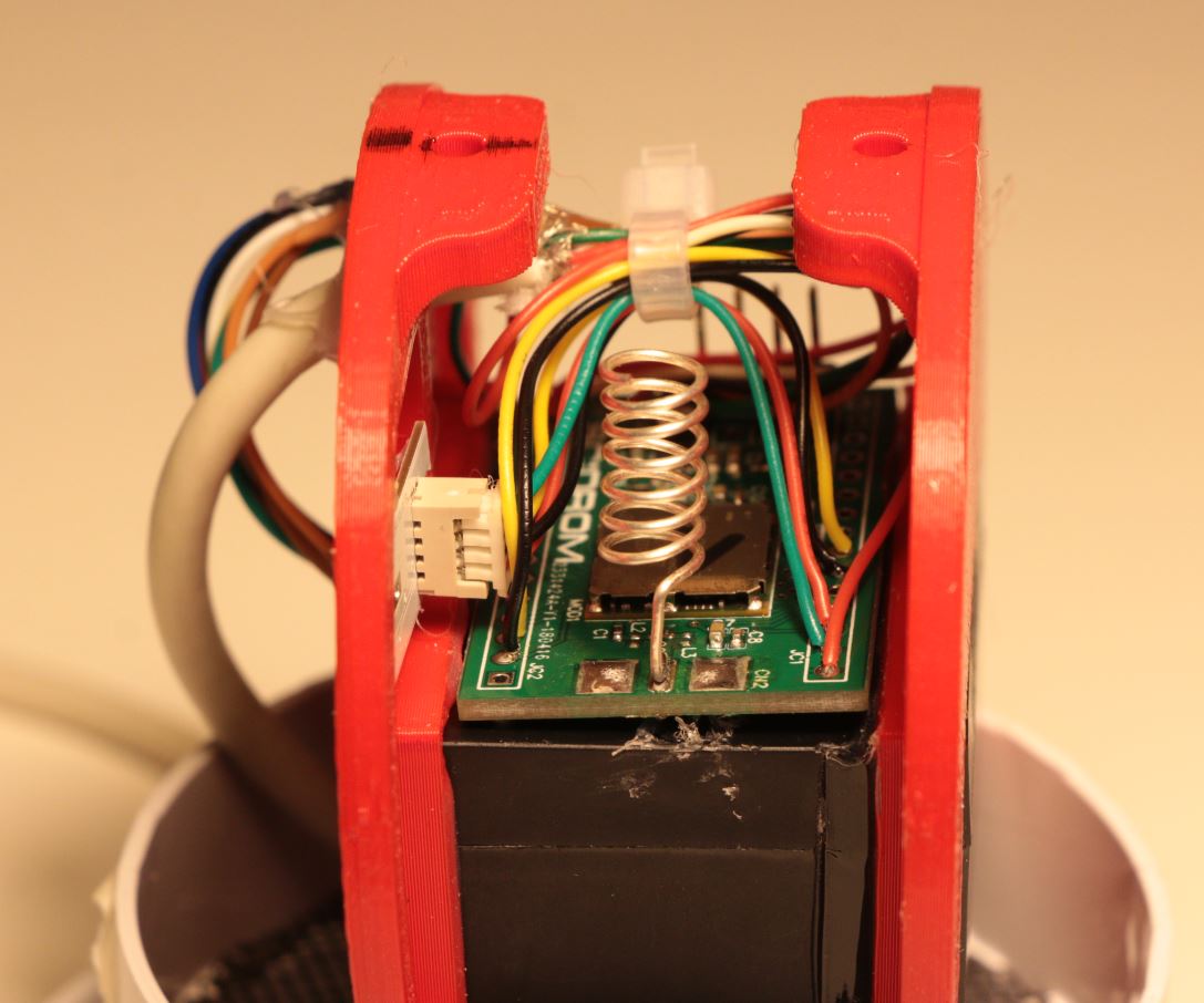
Small helical antenna
When extreme range is required, use SMA connector and external antenna (Yagi/Uda) for 868MHz.
Now solder all wires to the module and attach the module on the top of the HPM sensor.
Check if everything fits inside the plastic tube anclose it temporarly with vent grills. Place the power cable through the grill and secure it with one plastic tie:
Power cable goes through the grill

Finished and closed sensor
Setup
Use the source code from Github repository and open the application PM-Sensor from the Projects folder in free Keil IDE for STM32-F0 (Described here). Edit the comissioning file with the data from your TTN setup (just follow the instructions from the file). Bild the application and load the flash with ST-Link or anz STM32 evaluation board with integrated ST-Link. SWD pins are next to +5V/GND power input.
Don’t forget to add payload decoder in your TTN application.
Finished device and testing
I attached the sensor to half meter of the “L” aluminium profile for easier placement outdoor (see first photo in this post). If everything goes well, you should see readouts in the TTN application:

Decoded payload in TTN
Updates (September 2018):
After long field testing period I made some changes:
- Added pullup resistors for I2C: internal pullups are not OK
- Upgraded ST lorawan stack to version 1.2.0
- Removed all UART code for VCOM/diagnostic output and use UART for the HPM sensor only
- Added external transistor for switching power for the HPM sensor. Main purpose of this is to reset the HPM sensor when error is detected during readout. Switch is controlled with PA0 GPIO pin.
New interconnect schematic:
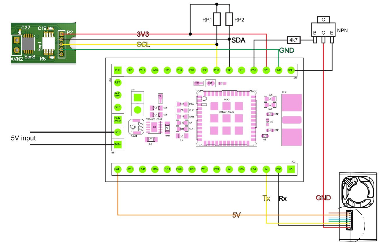
Updated PM sensor interconnect
Latest code for this sensor is here:
https://github.com/s54mtb/LoRaDunchy/tree/master/sw/Proj/LoradunchyPMsen