Multisensor LoRa interface module
A multisensor LoRa end device has been designed for connecting different sensors to LoRa network. It’s primary use can be LoRa weather station but is not limited only to enviromental applications.

Typical “weather” application is shown in image above: 1-LoRa sensor interface, 2-Particle sensor, 3-Sun shield with temperature and humidity sensors, 4-UV-index and illumination sensor, 5-solar panel for autonomous operation. Different sensors will be described separately. I hope this project could grow into different directions.
Sensor interface
Complete sensor interface consists of power management, communication and LoRa module with STM32 microcontroller. Interface is assembled inside plastic housing. PCB is suitable for mounting inside standard electrical installation junction boxes, exuiped with cable glands. This could be then used for outdoor applications with different enviromental sensors. Sensor interface module has several connections for sensors and different power sources. Complete system with all enviromental sensors is shown in following diagram:

Power management
Two power selectors provide automatic switchover between mains, solar or battery operation. Battery is managed with on-board Li-xx battery charger and Li-xx battery protection circuit. Both, the charger and protection circuit enable installation of single Li-xx cell without any electronics (e.g. single 18650 cell). Additionally, a low power fuel gauge is added for monitoring battery charge state, voltage, current and temperature. Voltage form selected power source is then regultated with Buck/Boost converter to 3,3V. Additional 5V supply is provided with boost converter for sensors requiring 5V supply. Complete power management is shown in following block diagram:
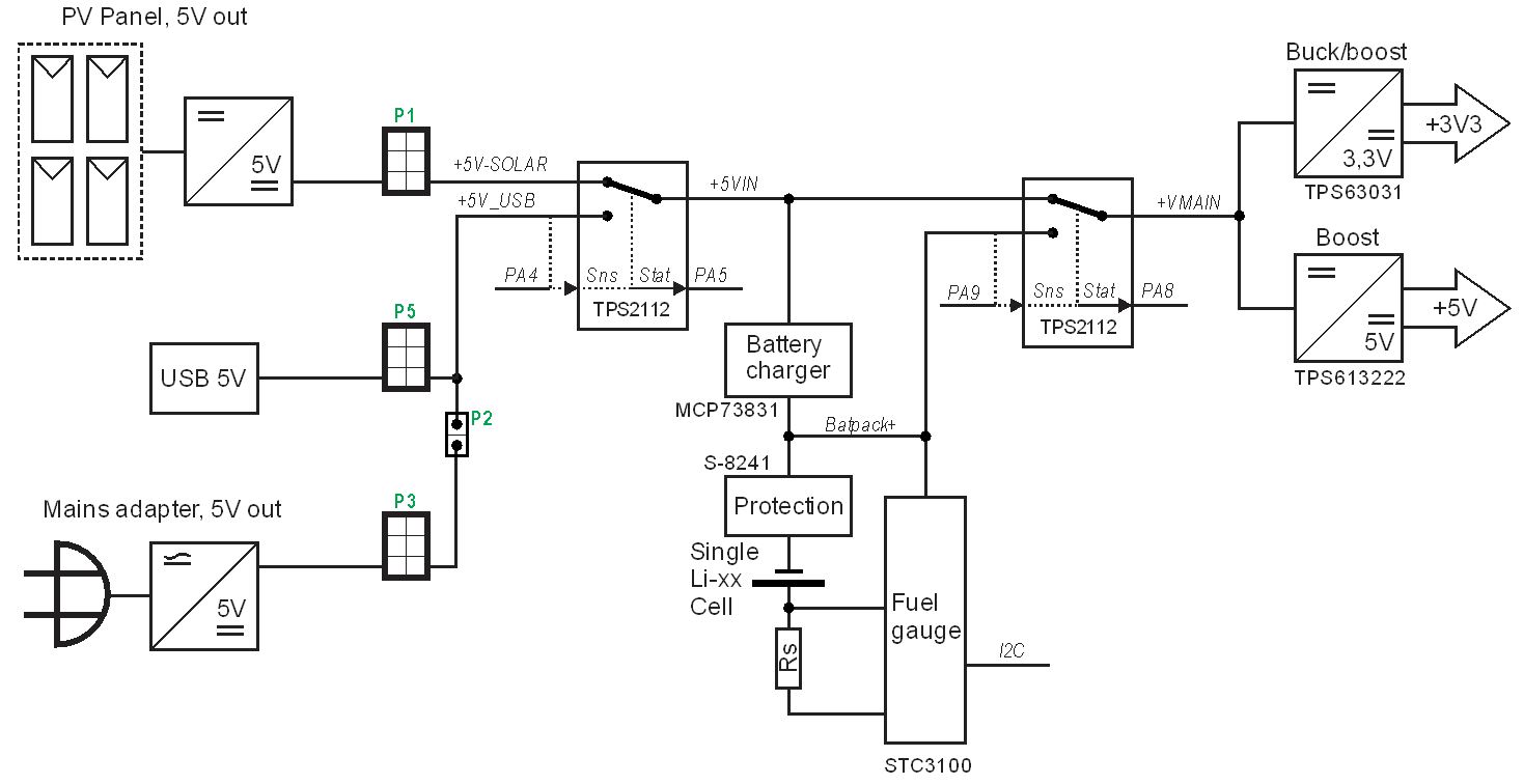
Current power source and charging status is reported to microcontroller via GPIO pins.
Schematic and PCB
Schematic diagram is shown below (download PDF here).

PCB is laid out with outline dimensions 65x65mm. Layout files are available. If interested, please request altium project file via email.
Assembled sensor interface module is shown in image below:

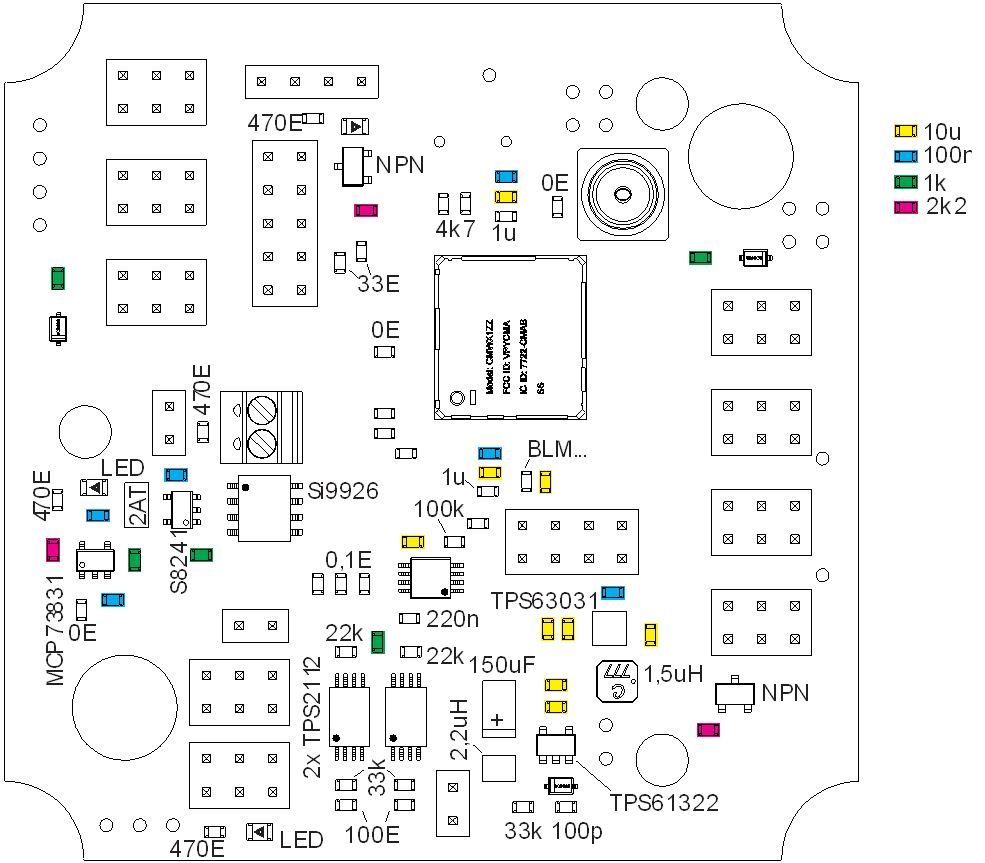
There are several connectors and test points on-board with following functions:

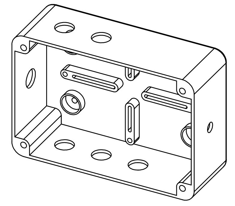
Housing
Module can be assembled inside standard junction box (recommended Gewiss GW44205 or similar). Assembly steps are shown below:
1. Drill 4 holes for bracket:
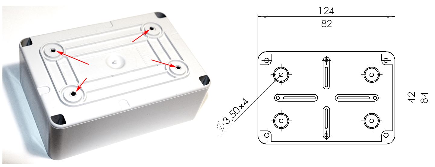
2.Drill holes for cable glands (PG7)
Cable glands locations are shown in the following drawing:

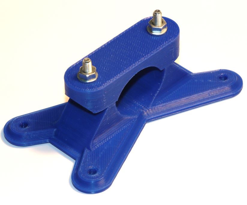
3. Use 3D printer and prepare bracket for the box:
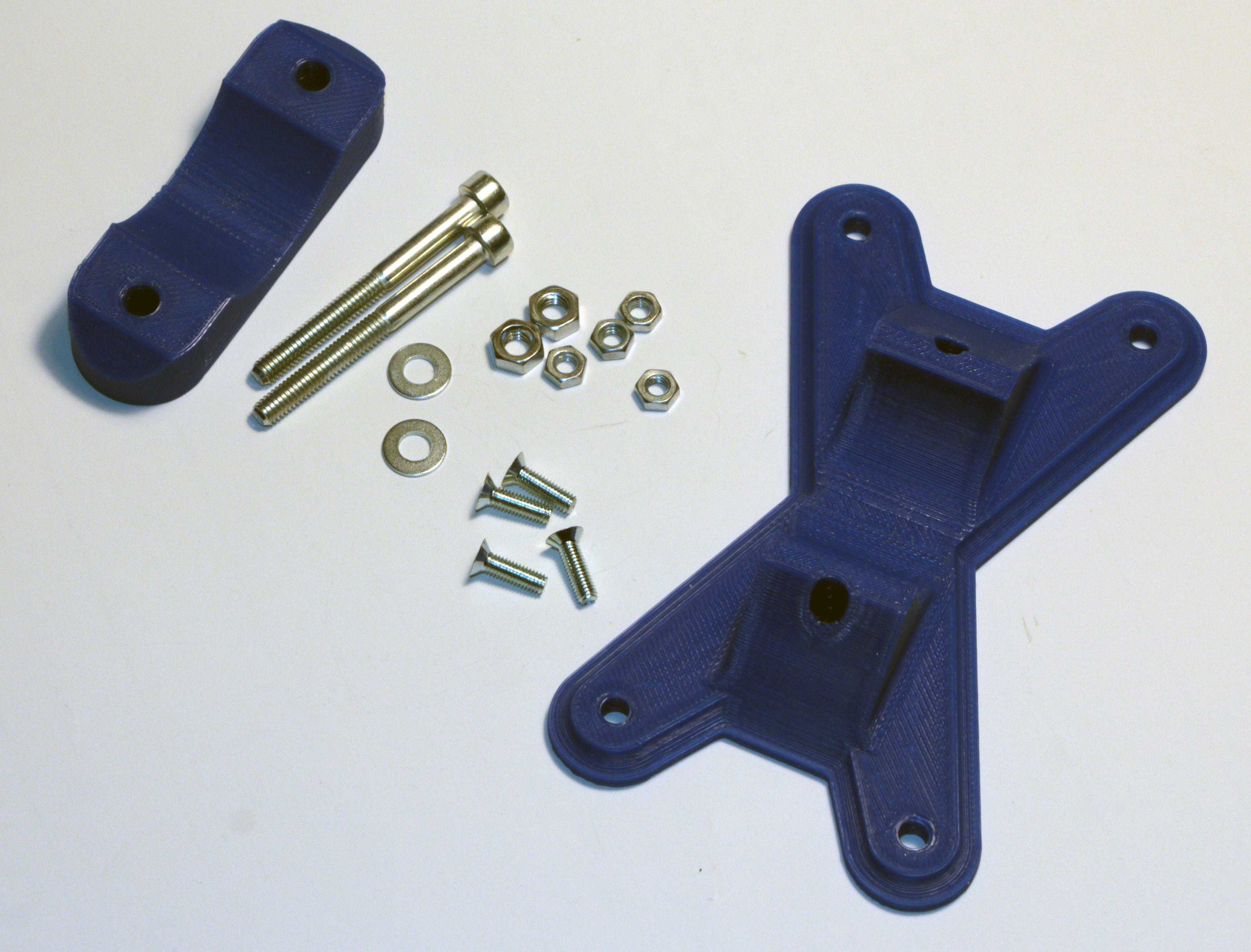
4. Attach bracket to the box

The external antenna is connected with pigtail with SMA connectors at each end.

Complete module is then placed on pole with outer diameter 30mm.

Testing LoRa communication
Currently there are only few sensors attached to the module: Particulate Matter sensor (PM10 and PM2.5), Humidity, Temperature, Air pressure and battery fuel gauge.
Here are few payloads decoded by TheThingsNetwork (TTN):
23:08:29 12 36 payload:24E57600009D9E0000 SHT_RH:40.605 SHT_Temp:30.437 channel:36
23:08:21 11 37 payload:25C07EF2412C472642974BBF47 BME280_PRESS:97943.1796875 BME280_RH:41.56950378417969 BME280_Temp:30.3118896484375 channel:37
23:08:05 10 38 payload:2675708440673706BB5A828CB80000FA4100000000 BATcharging:0 BATcurrent:-0.002047979971393943 BATrsoc:-0.0000670000008540228 BATtemperature:31.25 BATvoltage:4.13872766494751 channel:38
23:07:42  9 33 payload:2118001900 PM10:25 PM2_5:24 channel:33
The different sensors are sampled with different schedule and readouts are sent using dedicated data port in LoraWAN network. Currently the payload is decoded on 4 ports:
port 36 – SHT31 sensor (RH and T)
port 37 – BME280 sensor (RH, T and p)
port 38 – Battery status (U, I, Q, T, charging)
port 33 – HPM sensor (PM10, PM2.5)
The sensor data is sent either as scaled integer or float and decoded with the TTN decoder:
function Decoder(bytes, port) {
  // Decode an uplink message from a buffer
  // (array) of bytes to an object of fields.


///////////////// Decoder functions ////////////////////////////////
  // Based on https://stackoverflow.com/a/37471538 by Ilya Bursov
  function bytesToFloat(bits) {
    // JavaScript bitwise operators yield a 32 bits integer, not a float.
    // Assume LSB (least significant byte first).

    var sign = (bits>>>31 === 0) ? 1.0 : -1.0;
    var e = bits>>>23 & 0xff;
    var m = (e === 0) ? (bits & 0x7fffff)<<1 : (bits & 0x7fffff) | 0x800000;
    var f = sign * m * Math.pow(2, e - 150);
    return f;
  }
//////////////////////////////////////////////////////////////////////

  var decoded = {};

   if (port === 0x21) // PM Sensor
   {
     decoded.PM2_5 = bytes[2]<<8 | bytes[1];
     decoded.PM10 = bytes[4]<<8 | bytes[3];
   }

if (port === 0x24) // SHT31
   {
     decoded.SHT_Temp = (bytes[4]<<24 | bytes[3]<<16 | bytes[2]<<8 | bytes[1]) / 1000;
     decoded.SHT_RH = (bytes[8]<<24 | bytes[7]<<16 | bytes[6]<<8 | bytes[5]) / 1000;
   }


if (port === 0x25) // BME280
   {
		 decoded.BME280_Temp = bytesToFloat(bytes[4]<<24 | bytes[3]<<16 | bytes[2]<<8 | bytes[1]);
     decoded.BME280_RH = bytesToFloat(bytes[8]<<24 | bytes[7]<<16 | bytes[6]<<8 | bytes[5]);
     decoded.BME280_PRESS = bytesToFloat(bytes[12]<<24 | bytes[11]<<16 | bytes[10]<<8 | bytes[9]);
   }

if (port === 0x26) // Battery
  {
    decoded.BATvoltage = bytesToFloat(bytes[4]<<24 | bytes[3]<<16 | bytes[2]<<8 | bytes[1]);
    decoded.BATcurrent = bytesToFloat(bytes[8]<<24 | bytes[7]<<16 | bytes[6]<<8 | bytes[5]);
    decoded.BATrsoc =    bytesToFloat(bytes[12]<<24 | bytes[11]<<16 | bytes[10]<<8 | bytes[9]);
    decoded.BATtemperature = bytesToFloat(bytes[16]<<24 | bytes[15]<<16 | bytes[14]<<8 | bytes[13]);
    decoded.BATcharging = bytes[17];
  }
  decoded.channel = bytes[0];
  return decoded;
}
Complete software will be published on GitHUB repository after more testing and running for a while without issues.