19.04.2016, 21:19 by Mare
Today I started with realisation of some affordable weather sensors. First one is pluviometer or rain gauge. My idea is to attach some self draining container on the strain gauge. I salvaged one sensor from old kitchen scale (scrap from some other very interesting project).
First I drew my idea on paper:

Continue reading ‘Affordable pluviometer (rain gauge)’ »
Category:
Ham,
WX |
Comments Off on Affordable pluviometer (rain gauge)
19.04.2016, 06:28 by Mare
Biomedical signals originate from different sources. Bioelectric signals are generated by nerve and muscle cells. Each single cell under proper condition may generate an action potential, which is measured at single cell level or with more gross methods, where the electric field generated by the action of many cells is measured with surface electrodes at the body surface.
Bioimpedance signals are generated within tissue when excited by AC currents. The measurement is conventionally performed with four point method. Impedance changes are result of a tissue composition, blood volume and distribution, endocrine activity, sympathic nervous system activity, and other phenomena influencing body impedance.
Biomagnetic signals are generated by various bio-systems and organs. They generate weak magnetic fields which provides information not obtainable from other biosignal sources, like bioelectric signals. Biomagnetic signals has very poor signal to noise ratio
Some biomedical processes generate bioacoustic signals. These signals are usually acoustic noise. The measurement of noises provides information about underlying system. Typical noises are generated by blood flow of through the heart or hearts valves and blood vessels. Measurement of acoustic sounds generated by air flow through airways and lungs is one of the most important vital signs monitoring methods used also for special monitoring procedures. Characteristic sounds are also generated by digestive tract, joints, muscles or during pregnancy.
Biologic systems may generate Biooptical signals naturally or as a result of optical stimuli. Blood flow or blood oxygenation may be measured by light transmission and reflection at different wavelengths. Propagation of the fluids may be estimated when fluids are diluted with dye and dye appearance is measured with minimally invasive sensors like optical fibres.
Biomechanical signals are signals generated by displacement, pressure, tension, flow and others. Main difference between biomechanical and other signals is the biomechanical phenomenon does not propagate like electric and magnetic fields or acoustic signals through the tissue. This enforces invasive measurement techniques.
Chemical reactions between tissue or other live samples and other reagents usually result in different ion concentrations. Biochemical signals are result of such ion concentration deviation measurements performed with dedicated ion electrodes. Changes induced by biochemical reactions are in range of several seconds or minutes and could be treated as ”almost” DC signals.
18.04.2016, 19:38 by Mare
Medical electronics, mostly sensors, more specifically, Invasive blood pressure sensors are my professional occupation for last couple of decades. I gained some experience which I would like to share here. All new posts related to medical applications will have own category with some sub-categories which I will add “on the fly”. I will explain some basic sensing principles for several parameters measured on human (or animal) body. I will add some practical circuits I realized during my PhD study and could be interesting for hobby use.
I am really passionate about developing flexible, affordable and innovative solutions for healthcare, mostly low power and some simpler circuits or use of existing devices non-conventionally. My humble wish is that my expertise could be helpful to someone who visit my site.
Important information (disclaimer):
 The information contained in this website is for general information and educational purposes only. None of the circuits or other information presented in this site must not be used in any safety-critical applications (such as life support, diagnostic, therapetic treatment, etc…) where a failure of the presented circuits would reasonably be expected to cause personal injury or death. The readers and visitors of my site shall fully indemnify authors on this site against any damages arising out of the use of any circuits presented in this suite in such safety-critical applications . The reader of this site shall ensure that it has all necessary expertise in the safety and regulatory ramifications of its applications and the reader shall be solely responsible for compliance with all legal, regulatory and safety-related requirements concerning its products and any use of any information presented in this site own applications, notwithstanding any applications-related information or discussions that may be provided by this site.
Category:
Medical devices |
Comments Off on New section – medical electronics
04.04.2016, 11:52 by Mare
Branko, one of the famous experts for old(ish) radio devices designed magnetic loop antenna, which can be 3D printed. Here are complete instructions in german language:
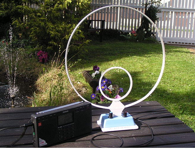
 Slovenski opis (in Slovenian language)
20.03.2016, 20:48 by Mare
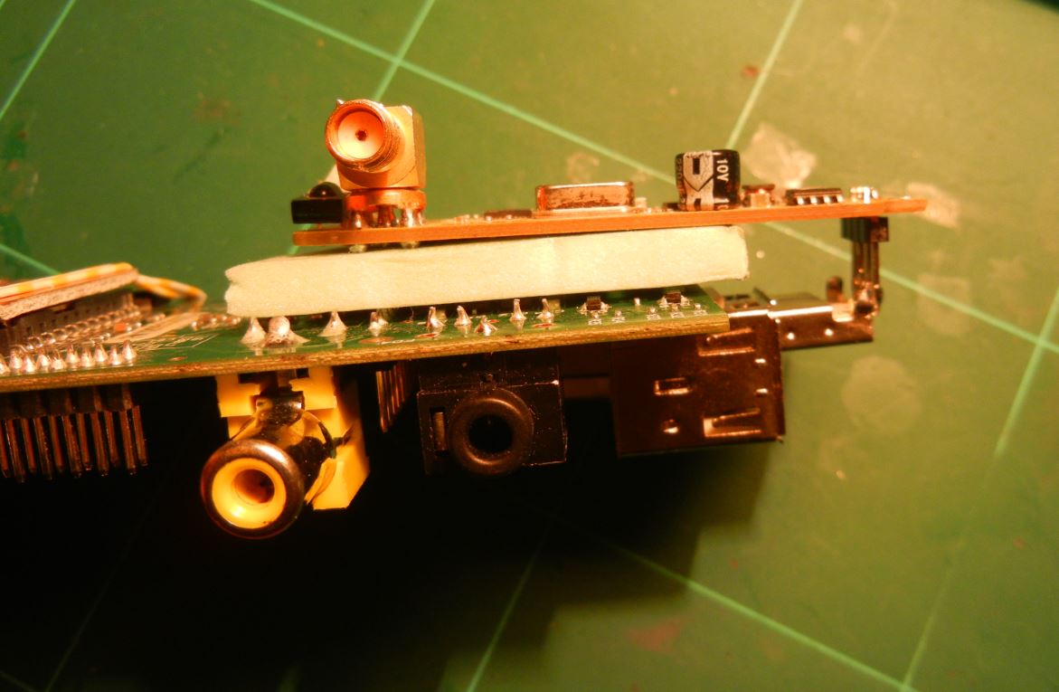
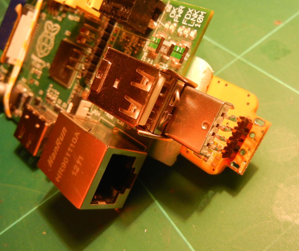
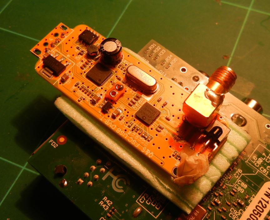
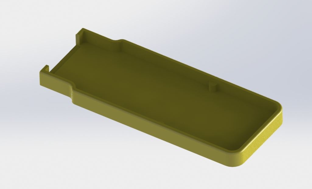
The R.Pi is excellent module for many applications. Unfortunately it is not easy to stack USB modules connected to it. When USB module, e.g. RTL-SDR is attached to the R.Pi, the whole package become very long requiring larger box. One solution is to use USB extension cable, but it again require additional space. Here is another, more compact solution:
- remove the USB connector from your module
- place SIL header at the pins for USB connector
- connect the USB module back “folded around the corner”


15.03.2016, 22:43 by Mare
I took old cover from plastic sewer pipe (it was never used ha ha). Then I drilled four holes for M3 screws and one bigger hole for camera module lens. The housing was prepared from one litre PET bottle. I cut the bottle to proper size and inserted raspberry Pi with the camera inside the bottle. Next the LAN cable with passive 5V “PoE” was inserted.
Finally, I heated the bottle with hot air gun at the camera side to shrink a little bit and tightly close the gap between the plastic camera “holder” and the bottle .
Photos below will tell more than thousand words:
Continue reading ‘Simple 5 minutes housing for Raspberry Pi with Camera’ »
04.03.2016, 13:24 by Mare
I was searching for 3D model of the STM32F7 discovery board (part number STM32F746 discovery) without success. I ended with my own 3D model.


>>>Here is the project on GRABCAD<<<
And local copy of STEP file: MB1191B-V14
29.02.2016, 23:35 by Mare
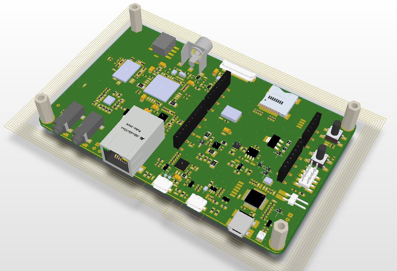
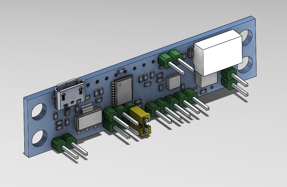
I designed dedicated PCB for the CW keyer. The project is very similar to the version made on prototyping board.


Here are the updates:
Continue reading ‘Mini CW Keyer / QRSS beacon V1.1’ »
28.02.2016, 00:33 by Mare
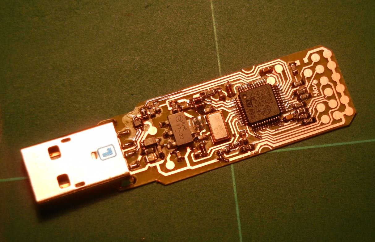
Today I found out how to “flash” blank STM32F103xC to make STLINK V2 debugger interface.
So, instead of desoldering from Discovery board to make miniture STLINK debug interface:


it’s possible to solder blank (or any) STM32F10x with USB and at least 64k flash + 20k RAM, program it with STLINK V2 Firmware and use your new USB dongle for debugging STM32 or STM8 devices.
Continue reading ‘How to program blank STM32F1 with STLINK V2 firmware’ »
24.02.2016, 22:26 by Mare